LED Protection

RustyH

Senior Member
Hello,

Just after some help if possible, Im making a small project circuit which uses a Cree CXA25 LED. 36v, 1.2A. I am supplying the power from a 36v power supply that I had spare, although its not regulated.

I was wondering what circuit should I put in place to protect the LED.
I read that you always put a Resistor in series, and the calculation for that is (Supply Voltage - LED voltage) / forward current. But if the LED voltage is 36v, and the power supply is 36v, then the calculation is zero?

Many thanks
 
Last edited:

papaof2

Senior Member
What voltage is the power supply with no load?
With the 1.2 amp load the LED would be?
The loaded voltage might be OK but it might need to be dropped. A non-regulated "36 volt" supply might be 40 volts or more with no load so you need to know what that voltage is under the planned load of 1.2 amps. A 30 ohm, 25 watt resistor would suffice as the load long enough for you to measure what the loaded voltage is. From that voltage you could compute the needed resistance, if any.
 

RustyH

Senior Member
Thank you

I will eventually want to drive two of these LEDs, so do I need to test for 2.4A, and therefore 15ohm load?

Am I also right in thinking it's the "Maximum Drive Current" value you use from the datasheet?

Cree Datasheet Link
 

papaof2

Senior Member
From the datasheet:
Forward voltage (@ 550 mA, 85 °C) 36V
Forward voltage (@ 550 mA, 25 °C) 42V

Note that this is at 19.8 watts at 85C and 23.1 watts at 25C. From the "Operating Limits" section of the datasheet, the allowable current depends on the temperature of the chip, with 1.2 amps being allowed up to about 95C but dropping to 1.1 amp at 100C, 1 amp at 110C and 0.55 amp at 125C. Be certain that you have a big enough heatsink and adequate cooling for the power level you plan to use. These specs are chip temperature which is difficult to measure, not heatsink temperature which is much easier to measure but requires some math to convert it to the chip temperature - the thermal resistance chip to heatsink and the thermal resistance heatsink to air must be included in those calculations.

The human eye is not guaranteed to see even increases in brightness from even increases in the amount of power applied to an LED. You might want to limit the current to the LED to around 0.5 amp and see how much light you have at the ~20 watt level - try that 30 ohm resistor in series with the LED.

Remember that you only have one chance in reaching the maximum current level of an LED at any given temperature - beyond that the LED acts like a fuse :-( Again, be certain that the LED has adequate cooling.
 

AllyCat

Senior Member
Hi,
I will eventually want to drive two of these LEDs, so do I need to test for 2.4A, and therefore 15ohm load?
Am I also right in thinking it's the "Maximum Drive Current" value you use from the datasheet?
IMHO it's much more complex than that. :(

Firstly, the forward voltage drop varies considerably with the LED temperature and can cause "thermal runaway" in some circumstances. Therefore you should use an individual "resistor" for each LED. The (maximum) "body" temperature of the LED is specified (on page 16 of the data sheet), so the maximum voltage and current you can use depends on the "size" (thermal resistance) of the heatsink that you attach. For example, for 1 Amp at 25 degrees C ambient, you need a Heatsink of about 3 degrees/watt.

Ideally, I would use a "Constant Current" Switching Mode Regulator (for each LED). Since the LED forward drop is similar to your Power Supply voltage, you might need a Buck/Boost regulator for maximum light output, but a simple Buck Converter might be sufficient (monitoring and stabilising the current flow from the voltage across a small resistor). A more sophisticated design might (also) monitor the LED-Heatsink temperature and control the current accordingly.

Cheers, Alan.
 

RustyH

Senior Member
Thank you ever so much for your replies.

These will be in sealed in aluminium housings and used underwater, so providing the thermal couple between chip and housing (heatsink) is good, and given the thermal mass of the water (which will never reach above 30 degrees C, and a volume of around 6000 litres), there thermals should be well managed.
However, I'm not sure how I could figure out what temperature the LED would run at in this environment?
 

inglewoodpete

Senior Member
When designing power sources for LEDs, particularly high-powered ones, you need to regulate (limit) the current. The supply voltage must be "adequate" ie. more than the LED's minimum turn-on voltage.

Unlike the traditional incandescent bulb, which increases its resistance as the voltage (and temperature) increases, LED's junction voltage (and resistance) reduces as it gets hotter. If the power source is not designed correctly, this can lead to thermal runnaway and destruction of the LED.

The following circuit snip is what I have used for lighting fascades of buldings (using 28X2 PICAXE PWM for RGB control). Circuitry on the left of the circuit, including Q23, is required if PWM dimming is required. Circuit on the right, up to and including ZD2, regulates the maximum current utilising Q24's Vbe. MOSFET Q4 requires a heatsink.

CurrentLimitedLEDDimmer.JPG4. 'Flourish' (Evening) FITZ Apartments LoRes.jpg
 
Last edited:

RustyH

Senior Member
Those Lights look brilliant

I may struggle to get a PCB inside the LED Aluminium Housing, so I may have to mount that type of protection circuit externally. Shouldn't be a problem.

Its likely, given it will be water cooled by a large volume of water that will probably never reach above 30 degree C, that I will kepe the LED cool enough to operate in that 1.2A range .

However, I don't necessarily need it to be on at full brightness, so I can back off the current a little to keep the LED happy.
So alternately, could I buy an LED driver as mentioned in post 7. These ones below might be more suited,

30 - 42V, Constant Current, 1.05A output

or

21 - 43V, Constant Current, 700mA output
 
Last edited:

AllyCat

Senior Member
Hi,
Would it be safer / easier if I drove each LED via one of these ........
Those two supplies have a "mains" (line) a.c. input, but the OP implied a 36 v d.c. input ? Is this a "mobile" (e.g. battery-powered) application, or something like an aquarium? Note in the graph on page 9 of the Data Sheet that the LEDs need about 40 volts at 25 degrees C for 1 Amp, which falls to about 38 volts when they "warm up" to 105 degrees.

You should be able to estimate the heating because more than 50% of the electrical energy will (still) be converted to heat. My first Google for "best LED efficiency" found THIS LINK which includes the following (and then suggests even greater losses in practice):
"While energy conversion efficiency of incandescent lamps, for example, is between 10 % and 20 %, very efficient LEDs at present achieve values between 40 % and 50 %. Nevertheless, this is still only 40 – 50 %, so 50 % to 60 % of the power is lost as heat."

Thermal calculations are generally quite similar to Ohms Law (hence the term Thermal Resistance) with the Heat Flow equivalent to Current and Temperature equivalent to Voltage, but unfortunately even members on this forum don't always understand (or can use) Ohms Law. :(

Finally, I feel I should clarify the terms "PWM" (Pulse-Width-Modulation), "Switching Mode" or "Class D" (amplification), because there are two fundamentally different types (depending on whether an inductor is used or not). In the "simple" version (as in post #8) the LED is switched On and Off rapidly so that the average current (and brightness) is reduced, but the "instantaneous" (or peak) current/brightness is determined by (all) the resistance(s) in series with the Supply Rail. This means that some power is "lost" in the series resistance (which might be more "inconvenient" than in the LED which can have good Heat Sinking), and the illumination may "flicker" (depending on the PWM frequency).

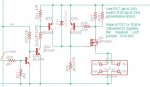
However "real PWM" (as I call it, because I worked on it for many years :) ) uses an Inductor to "store" the surplus energy (voltage) and then applies it to the load (LED) via a Recovery Diode, during the "Off" (i.e no input current) period of the PWM cycle. Thus the current in the LED is "continuous", so there should be no flicker and the LED can be brighter because the "peak" current flow may be lower. This type of PWM often operates at 100 kHz and upwards, to allow the inductor and supply (decoupling) capacitors to be much smaller. Most dc-dc converters (and some audio amplifiers now) use this principle.

Cheers, Alan.
 

inglewoodpete

Senior Member
Those Lights look brilliant

I may struggle to get a PCB inside the LED Aluminium Housing, so I may have to mount that type of protection circuit externally. Shouldn't be a problem.

Its likely, given it will be water cooled by a large volume of water that will probably never reach above 30 degree C, that I will kepe the LED cool enough to operate in that 1.2A range .

However, I don't necessarily need it to be on at full brightness, so I can back off the current a little to keep the LED happy.
So alternately, could I buy an LED driver as mentioned in post 7. These ones below might be more suited,

30 - 42V, Constant Current, 1.05A output

or

21 - 43V, Constant Current, 700mA output
I derate the supply current to high-power LEDs in my installations to about 80% of the sepecified maximum. The difference in light output is barely noticable.

I have found it is best to mount the control equipment remotely from the lights. My reason for using a P-channel MOSFET in the current-limited supply inside the building is to have the limiting performed on the positive leg. If the worst should happen, like the +ve lead coming in contact with a grounded object, the power source will limit the output current to what would be supplied to the LEDs - no fuses get blown.

In the installation shown in the photo above, the controller and power source are in an electrical cabinet in the car-park, under the building. Low-voltage (about 45 volts) DC cabling connects the two. Installed August 2016, still going strong.
 

RustyH

Senior Member
Sorry, My apologies, Yes, I should have said, was thinking those LED drivers would replace the 36V PSU which is a 240v plug in PSU.
These will indeed be mounted in a Pind application
 
Last edited:

AllyCat

Senior Member
Hi,

There are a lot of advantages in not trying to "Reinvent the Wheel". It appears that the RS and CPC supplies that you've identified are intended to drive LEDs in an "optimal" way, so the price is not excessive (but you might find cheaper from a non-specialist retailer). The ">86% efficiency" indicates that they very probably use "real" PWM and their Constant Current mode is exactly what LEDs need (unless you want a dimming capability).

If you attach both LEDs very intimately to the same Heatsink, then you should need very little, or even no, series resistance because if one LED dissipates more power than the other, it will heat up both LEDs, avoiding the likelihood of its thermal runaway.

Cheers, Alan.
 

RustyH

Senior Member
Thank you for all the help again, very very informative and appreciated.

The 2 LEDs will actually be 2 Seperate Lights, each in there own housing. So each housing will only need to dissipate the heat of 1 LED
 

AllyCat

Senior Member
Hi,
The 2 LEDs will actually be 2 Seperate Lights, each in there own housing.
In that case it might be better to use a separate power supply for each LED.

Alternatively, a series resistor dropping probably 1 - 2 volts to each LED should be suficient (depending exactly how hot the LED bodies get). But an adjustable-current supply (with a "preset" control of some form) might be more flexible if you can find one. ;)

Cheers, Alan.
 

AllyCat

Senior Member
Hi,

I thought those supplies looked suspiciously like the "chokes" used in the old Fluorescent Tube luminaires. It appears that they use a Thyristor/SCR to control the current/brightness, so the LED will still flicker at 100 Hz (and they are said to be "compatible" with conventional Dimmers).

They're probably suitable for driving the Cree LEDs, but we ought to check that their characteristics are not too different from the "LED Tubes" now being used to replace the traditional Fluorescent Tubes.

Cheers, Alan.
 

RustyH

Senior Member
Hi Alan,

I'm not planning on dimming them LEDs, just run then at a constant brightness. Will that help?

The VTAC one is none dimmable
CPC sell the same one for less - VTAC 6004
 

AllyCat

Senior Member
Hi,

I suspect all those supplies are quite similar (with just differences in their "ratings"). But 42 watts (i.e. 40 v * 1.05 A from the graph on page 9) is quite a lot of power to feed into "one" LED. Perhaps 16 watts would be output as Light and 26 watts must come out via the Heatsink. That's why I was considering a Dimming capability to "throttle back" the power for testing. Those supplies appear to be primarily intended to drive LED panels that are 600 mm square!

Don't forget that to reduce/share the power from a Constant Current supply you must use a parallel connection, not a series resistor! For example a 150 ohm resistance across the LED would offload about 11 watts (i.e. V2 / R = 1600 / 150 ) away from the LED. Or you could use a resistor of perhaps 2 ohms in series with each LED and run two in parallel from the same supply. That should reduce the risk of destroying (i.e. overloading) a single LED (but opens the small possibility of destroying two :( ).

If you don't have a suitable temperature sensor, you can try the "Dry and Wet Finger" tests: Try to avoid a Dry Finger dabbed onto the hottest part of the heatsink/LED being "too hot to touch", and switch off immediately if a Wetted finger sizzles :) Perhaps I'm being over-cautious, but I guess those Cree LEDs aren't cheap. ;)

Cheers, Alan.
 

RustyH

Senior Member
On R25, the range is 4. 7k to 27k, is there much affect in the circuit at min and max of that range?


When designing power sources for LEDs, particularly high-powered ones, you need to regulate (limit) the current. The supply voltage must be "adequate" ie. more than the LED's minimum turn-on voltage.

Unlike the traditional incandescent bulb, which increases its resistance as the voltage (and temperature) increases, LED's junction voltage (and resistance) reduces as it gets hotter. If the power source is not designed correctly, this can lead to thermal runnaway and destruction of the LED.

The following circuit snip is what I have used for lighting fascades of buldings (using 28X2 PICAXE PWM for RGB control). Circuitry on the left of the circuit, including Q23, is required if PWM dimming is required. Circuit on the right, up to and including ZD2, regulates the maximum current utilising Q24's Vbe. MOSFET Q4 requires a heatsink.

View attachment 25463View attachment 25464
 

inglewoodpete

Senior Member
The value of R25 depends on the lighting supply voltage. We use 10W LEDs, which drop around 11 volts each. So, when daisy-chaining (up to) 5 x 10W LEDs, it needs around 55 volts.

R25 is a 1/4 watt pull-down resistor which is used to turn the P-channel MOSFET on. The resistance value is not critical but I use about 5k per 11 volts.

The Cree LED you mentioned in your original post requires around 36 volts, so I'd recommend 15k for R25. If it seems to be getting too hot, try 18k.
 
Top