LED matrix 4x4 and 74HC595 help

Hello,

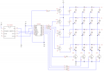
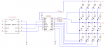
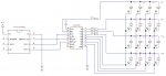
I would like to ask for help. Can I wire a circuit like the one in the attached image? If yes, I cannot figure out what a code looks like if I want to multiplex LEDs in the matrix so that only one is "ON" at a time and to run various animate patterns. Could anybody be willing to explain it to me? Thank you very much for help. I can (almost) figure out doing it with two 74HC595 in cascade only.
 

Attachments

westaust55

Moderator
Before getting down to the software, if I may make a few commands about the circuit.

You are driving 1 to 4 LEDs via a single outputs aiming say Red LEDs with 2 Volts for Vf
Then with 1 LED on it will have 15 mA passing. With 4 LEDs operating one an output, each LED will carry about 4mA so there will be a difference in brightness levels. Actual current will be less as there will be some fraction of a volt drop within the 74595.

Next the '595 is rated for 70 mA absolute max betting to keep to around 50 mA.
The reason is internal ratings and heat generated due to through current.
Will all LEDs on, that is around 4 x 15 = 60 mA on the first 4 pins and in terms of heating the same again for the other 4 outputs sinking current.

There is nothing wrong with using a 74595 as a driver chip but with so many LEDs, use a transistors as drivers on high and low side of the LEDs would be good along with individual resistors for each high side line.

BC548 will do for low side and BC558 for high side switching with say a 1 kOhm base resistor to each transistor. These transistors are rated to 200 mA each.
 
As I didn't get the concept of controlling the matrix, I count with current for only 1 LED. Now it is becoming clear that I have to count with 4 LEDs being ON simultaneously. In case of 8x8 matrix it would be 8 LEDs ON at the same time, right? I attached a new drawing, hoping that it is correct, for those who could benefit from it as well.

EDIT: I replaced the attached image with correct circuit diagram. Inside the zip file there is circuit drawing editable in TinyCAD for those who would like to make some modifications.
 

Attachments

Last edited:

AllyCat

Senior Member
Hi,

In the second diagram, you also need a 1k resistor in series with each NPN base. 1k for all the base resistors is probably slightly lower than necessary, but will work fine.

With 330 ohm series resistors, the four NPNs are hardly necessary, each 595 pin should be able to pull down about 10 mA (only one of the PNPs will be turned on at a time). Or for 16 LEDs, you could consider an 8 x 2 multiplex, with just two "pullup" PNPs, perhaps activated by one or more of the "control" lines (data/clocks) from the PICaxe. That potentially drives the LEDs "brighter" (50% instead of 25% duty cycle) and gives simple byte-wide loading for the 595.

Also, if you are using an HC type device, you should bias the /OE and /MR inputs (i.e. connect to GND or Vcc as required, preferably via a resistor) for correct/reliable operation.

Cheers, Alan.
 

AllyCat

Senior Member
Hi,

... only one is "ON" at a time and to run various animate patterns.
If you only want one LED alight at a time, then your original design will probably be OK and the code is not too hard. Lighting several LEDs at the same time is more difficult.

The key is to understand how the variables b0 - b3 can be controlled (and read) as separate bits (bit0 to bit31):

First, create an "image" of the data that you need to put into the 595, for example in b0. Typically, one of the bits in the High nybble (bit4 - bit7) will be cleared to a '0' to select the "column" (of the LED) and one of the bits in the Low nybble (bit0 - bit3) set to a '1' to select the "row".

Then you need to transfer the data from b0 into the 595. This can be done with a program loop, copying the top bit (bit7) to the "data" pin, pulsing the clock pin, then shifting the byte left (multiply by 2) and repeating 8 times. Alternatively, it can be faster to use "linear" code, explicitly copying each bit and pulsing the clock to the port pins.

Here is some untested "pseudocode"; I'll leave you (or perhaps some other kind person) to define all the pin names and correct pulse polarities, etc.:

Code:
for b4 = 0 to 7
	if bit7 = 0 then 
		Low DS
	else
		High DS
	endif
	pulsout SRCLK,1		; Store the bit in the Shift Register
	b0 = b0 * 2		; Shift bit6 to bit7, etc.
next b4
pulsout RCLK,1			; Copy the byte to the output pins
Cheers, Alan.
 

westaust55

Moderator
Let's say we allow for 15 mA per LED so a total/max through a transistor of 60 mA. Normal transistor gain will be 200+ but in saturation will be of the order of 20 so base current of 60 / 20 = 3 mA.
PICAXE IO will always be down a little from supply rails and allow 0.7 volts for transistor base to emitter so with 5 V supply the base resistor volts will be around 5 - 0.9 volts = 4.1 volts.
For our 3 mA base current we need a max of 4.1 / 0.003 ==> 1.3 kOhm max so a 1 kOhm resistor is good or a 1.2 kOhm.

With transistor in saturation Vce will be around 0.2 volts .

So again presuming LED has Vf of 2 volts resistor will have
5 - (2 x 0.2 + 2) = 2.6 volts.
To allow 60 mA need a resistor of 2.6/0.06 = 43 Ohms
But as mentioned in post 2 this will result in different LED brightness, so a better solution is a 150 Ohm or 180 Ohm resistor is series with EACH of the LEDs.
 

westaust55

Moderator
For coding, one part is to have a routine to shift the data to the 74HC595.
As well as the example by AllyCat above if you look under the SHIFTOUT command in PICAXE manual 2 there is a similar example for non X1/X2 parts such as M2 that do not have inbuilt shift command.

I posted long ago a 3-digit disagree driven by 74HC595 chips. Search for that and see if you can work out what to extract for your display.
 

AllyCat

Senior Member
Hi,

I think the OP needs to summarise exactly what he is trying to achieve. In the first post he may have caused confusion by using the word "multiplex" (which normally implies that more than one LED appears to be ON at the same time) but says that "only one is ON at a time". For that situation, the original diagram is adequate (the current in one LED will be about 10 mA, which should be bright enough because it can have 100% duty cycle) and the code quite simple (the diagram shows an 08M2).

However, in #3 he refers to lighting 4 diodes together and also to driving an 8 x 8 matrix array. The hardware and software for those situations will be very different, because the whole array has to be continuously updated about 50 times every second, with each LED pulsed on for only a few ms each time. For an 8 x 8 array, both row and column drivers are probably needed (16 transistors) and the PICaxe may struggle to avoid "flicker", even at a higher clock speed (setfreq m32).

Cheers, Alan.
 
I am back. I am sorry for having caused confusion. I myself am still confused with the whole concept of running LED matrix. Anyway, I am going to explain what I want to learn with your kind help. For the beginning I would like to make various patterns by lighting one LED at a time using principle called persistence of vision. I hope I did not mixed two cocepts again by saying this. It should be possible, right? This will be my first task. I want to put the whole circuit on stripboard, this will take some time to do it. So if you can push me in that direction. The base for such a piece of code is in the post #6, isn't it?
 

AllyCat

Senior Member
Hi,

The PICaxe is very slow (compared with assembler or a compiled language), particularly if using a shift-register to control the LEDs. Therefore, trying to use "persistence of vision" with only one LED "on" at a time is likley to cause flicker (and low apparent brightness). It may be OK if each of your "patterns" has no more than 3 or 4 LEDs apparently ON. But for anything more, then you should use a conventional multiplex (selecting each row or column in sequence and switching ON all the appropriate LEDs in that row/column).

Typically, your program would need to create 4 "image" bytes which each select (all) the ON LEDs for one row or column (depending on the hardware connections). Then, you will need some fast "background" code (but it will probably use most/all of the PICaxe's processing time) that writes the correct "image" byte to the 595, approximately every 5 ms (using a timing loop or an interrupt).

Cheers, Alan.
 

westaust55

Moderator
I concur with AllyCat that driving an entire row or column at a time/step is the better way to go.

Ages ago now I did an 8x8 RGB matrix (192 LEDs)but used i2c and i2c IO expander chips and just 8 step each of 24 LEDs to complete a frame. Project is posted on the forum.
That was faster than the X1 inbuilt SHIFTOUT which in turn was from memory 4 times faster than bit bang shift code.
That still had some flicker at 8 MHz so you would need to have the PICAXE running at something like 32 MHz on an M2 and doing little else to minimize flicker.
 
It seems that having one LED "on" at a time is a bad idea due to PICAXE speed. I will use an entire row or column at a time then. So, how should I begin coding if I want to display letter "I" that consists of only 1 column (4 LEDs) lit? The second task will be rotating letter "I". What do you suggest?
 

AllyCat

Senior Member
Hi,

We can't really help any more with coding until we know the exact external circuit (pullup PNPs only, or PNP + NPN drivers?). For that, you may need to do some simple tests to find out how much current your LED(s) need to give "satisfactory" brightness. Sometimes "superbright" LEDs are cheaper than adding driver transistors !

A 4 x 4 matrix is very limiting to display "Letters" (ASCII characters). Generally 5 x 7 is considered the minimum, 4 x 6 occasionally acceptable and 3 x 5 (which could use the outputs from a single 595) can do "most" characters (but not rotated by 90 degrees), including all the numbers in a "7-segment" format. You don't need any hardware (except a piece of paper or perhaps a computer screen with Courier Font) to experiment with what is possible. For example (0 = LED on) :


- - 0 - | - - - - (row1)
- - 0 - | - - - - (row 2)
- - 0 - | 0 0 0 0 (row 3)
- - 0 - | - - - - (row 4)


Also "interesting" is a 5 x 5 array, because 5 bits (from the 595) can drive all the rows (or columns) with the other 3 bits defining a binary number (0-7) which can select the appropriate column (or row) using simple hardware decoding.

- - 0 - -
- 0 - 0 -
0 0 0 0 0
0 - - - 0
0 - - - 0


Cheers, Alan.
 
Thank you. I will try some experiments with the circuit I posted here, maybe I will expand it to 5x5 LEDs. It will take some time and then I will let you know my either positive or negative experience.
 
I am back. So far I made 4x4 LED matrix without transistors, see attached circuit. I wrote a code that displays letter A and O in loop with a pause between them. It seems to me that my code is dull or heavy if it is the right english word.
Here it is:
Code:
REM u 08M2 se pouziji piny C.0, C.1 a C.2
REM pin C.0 je propojeny s pinem 12 RCLK (Storage Register Clock) - pri prechodu z LOW na HIGH se zobrazi data
REM pin C.1 je propojeny s pinem 14 DS (Data) – nabira postupne 8 bitu pro registr
REM pin C.2 je propojeny s pinem 11 SRCLK (Shift Clock) – pri prechodu z LOW na HIGH posune data o 1 bit
setfreq m8
low 0
low 1
low 2
REM nacteni hodnot do EEPROM pameti mikrokontroleru

eeprom (%11101110,%11010101,%10110101,%01111110,%11110000,%11110000,%11110000,%11110000,%11101111,%00101001,%01001001,%01111111)

do

for b4=0 to 20
    for b1=0 to 3
	read b1,b0	
	pin1 = bit7
    	pulsout 2, 5
    	pin1 = bit6
    	pulsout 2, 5
    	pin1 = bit5
    	pulsout 2, 5
    	pin1 = bit4
    	pulsout 2, 5
    	pin1 = bit3
    	pulsout 2, 5
    	pin1 = bit2
    	pulsout 2, 5
    	pin1 = bit1
    	pulsout 2, 5
    	pin1 = bit0
    	pulsout 2, 5	

    	pulsout 0, 5
    			
    next b1
next b4	

for b4=0 to 30
    for b1=4 to 7	
	read b1,b0	
	pin1 = bit7
    	pulsout 2, 5
    	pin1 = bit6
    	pulsout 2, 5
    	pin1 = bit5
    	pulsout 2, 5
    	pin1 = bit4
    	pulsout 2, 5
    	pin1 = bit3
    	pulsout 2, 5
    	pin1 = bit2
    	pulsout 2, 5
    	pin1 = bit1
    	pulsout 2, 5
    	pin1 = bit0
    	pulsout 2, 5	

    	pulsout 0, 5		
    next b1
next b4	

for b4=0 to 20
    for b1=8 to 11
	read b1,b0		
	pin1 = bit7
    	pulsout 2, 5
    	pin1 = bit6
    	pulsout 2, 5
    	pin1 = bit5
    	pulsout 2, 5
    	pin1 = bit4
    	pulsout 2, 5
    	pin1 = bit3
    	pulsout 2, 5
    	pin1 = bit2
    	pulsout 2, 5
    	pin1 = bit1
    	pulsout 2, 5
    	pin1 = bit0
    	pulsout 2, 5	

    	pulsout 0, 5
    			
    next b1
next b4

for b4=0 to 30
    for b1=4 to 7	
	read b1,b0	
	pin1 = bit7
    	pulsout 2, 5
    	pin1 = bit6
    	pulsout 2, 5
    	pin1 = bit5
    	pulsout 2, 5
    	pin1 = bit4
    	pulsout 2, 5
    	pin1 = bit3
    	pulsout 2, 5
    	pin1 = bit2
    	pulsout 2, 5
    	pin1 = bit1
    	pulsout 2, 5
    	pin1 = bit0
    	pulsout 2, 5	

    	pulsout 0, 5		
    next b1
next b4

loop
Is there a better way to write such a code doing what I described above?
 

Attachments

hippy

Technical Support
Staff member
Your "for b4 / for b1" loops are near duplicates of each other so it seems possible to have one loop and pass the values into the loop held into a subroutine ...

Code:
Do
  b14 = 20 : b11 = 0 : Gosub DisplayFrame
  b14 = 30 : b11 = 4 : Gosub DisplayFrame
  b14 = 20 : b11 = 8 : Gosub DisplayFrame
  b14 = 30 : b11 = 4 : Gosub DisplayFrame
Loop

DisplayFrame:
  b12 = b11 + 3
  for b4=0 to b14
     for b1=b11 to b12
     :
     next b1
  next b4
  return
 
Top