I constructed the "LDR SWITCHING" circuit on a PROTO BOARD but for some reason it is just failing to do so.
- see attachment- The Flow chart works perfectly.
WORKING OPERATION
A light source is to strike the LDR placed in a dark box in a sequence namely- Three exposures to the light each exposure lasting approximately 15 seconds ( count from 1 to 30 ).
At the end of the third exposure outputs "0" and "1" should go high for two seconds each in turn after a wait of two seconds
After a time lapse of 120 seconds the sequence resets ie if one exposure is made and more
120 seconds passes the out puts would not go high with two subsequent exposures all because
the event did not take place within the 120 seconds time frame. The System resets ready to start all over again.
WHAT I HAVE DONE SO FAR.
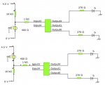
On the PROTO BOARD I have tried both pull up and pull down configurations with the 10K
RESISTOR but it is either not working or working how it is not suporsed to
I tried varying the range of the analogue sensor and again it is either not working or working how it is not supposed to.
As a matter of fact when the LDR is in the uppermost position in the voltage divider without any light exposures the outputs would go high for long periods on its own.
MY SUSPICION
I read somewhere in one of the manuals and it was said that the 10K Resistor is not necessary on the PROTO BOARD but I am not sure.
Secondly I suspect I am missing something that is very fundamental to connecting the circuit.
Any help or advise on resolving the above would be greatly appreciated.
- see attachment- The Flow chart works perfectly.
WORKING OPERATION
A light source is to strike the LDR placed in a dark box in a sequence namely- Three exposures to the light each exposure lasting approximately 15 seconds ( count from 1 to 30 ).
At the end of the third exposure outputs "0" and "1" should go high for two seconds each in turn after a wait of two seconds
After a time lapse of 120 seconds the sequence resets ie if one exposure is made and more
120 seconds passes the out puts would not go high with two subsequent exposures all because
the event did not take place within the 120 seconds time frame. The System resets ready to start all over again.
WHAT I HAVE DONE SO FAR.
On the PROTO BOARD I have tried both pull up and pull down configurations with the 10K
RESISTOR but it is either not working or working how it is not suporsed to
I tried varying the range of the analogue sensor and again it is either not working or working how it is not supposed to.
As a matter of fact when the LDR is in the uppermost position in the voltage divider without any light exposures the outputs would go high for long periods on its own.
MY SUSPICION
I read somewhere in one of the manuals and it was said that the 10K Resistor is not necessary on the PROTO BOARD but I am not sure.
Secondly I suspect I am missing something that is very fundamental to connecting the circuit.
Any help or advise on resolving the above would be greatly appreciated.