LCD Serial Display

jc173

Member
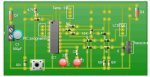
I've got a PCB, soldered on 3 flying wires going to the Serial LCD and used the following BASIC syntax as a test

Code:
main:
          serout 7, N2400, ("Test 1 2 3")
          goto main
When everything is switched on it is not working at all.

I have run test codes to check the other in/output devices work and they all do, i've replaced the screen with another screen....

any ideas?


TIA


James
 

westaust55

Moderator
James,
try adding an extra line
PAUSE 500​
at the start before the SEROUT command.
Can try longer than 500 if you want

That will give the display time to initialise.
Next step would be to send a reset command to the LCD (read the LCD manual to find out how to do that)

Just to make sure you are on the right track:
which PICAXE chip are you using?
Which physical pin is the LCD connected to?
 

jc173

Member
If you get nothing at all on the screen don't forget the contrast adjustment!

Thanks for that, have been playing with that to ensure it's right

James,
try adding an extra line
PAUSE 500​
at the start before the SEROUT command.
Can try longer than 500 if you want

That will give the display time to initialise.
Next step would be to send a reset command to the LCD (read the LCD manual to find out how to do that)

Just to make sure you are on the right track:
which PICAXE chip are you using?
Which physical pin is the LCD connected to?
ok, pause 500 will try that :)

Micro controller is a PICAXE 18A
it's on physical pin 13 which is I/Put 7 :)
 

eclectic

Moderator
@James.
I don't have an 18A, so I used an 18X

AXE091 board / AXE033 LCD
Power = 4 x NiMh AA ~ 4.97v

The following four programs all work, producing screen output.
Code:
main:
          serout 7, N2400, ("Test 1 2 3")
          pause 1000
          goto main
          
################          
  main:  
  serout 7, N2400, ("Test 1 2 3")
          pause 1000
          goto main
          
#################          
  
  serout 7, N2400, ("Test 1 2 3 *")
          pause 1000
          goto main
  
##################  

serout 7,n2400,(254,1)
pause 50
main:
 serout 7, N2400, ("Test 1 2 3")
          pause 1000
          goto main
I then changed power supply to three slightly used AA (~ 4.4v)
= NO display.

Please check your PCB wiring and your power supply.

The AXE033 needs ~ 5.0 v.

e
 

jc173

Member
@James.
I don't have an 18A, so I used an 18X

AXE091 board / AXE033 LCD
Power = 4 x NiMh AA ~ 4.97v

The following four programs all work, producing screen output.
Code:
main:
          serout 7, N2400, ("Test 1 2 3")
          pause 1000
          goto main
          
################          
  main:  
  serout 7, N2400, ("Test 1 2 3")
          pause 1000
          goto main
          
#################          
  
  serout 7, N2400, ("Test 1 2 3 *")
          pause 1000
          goto main
  
##################  

serout 7,n2400,(254,1)
pause 50
main:
 serout 7, N2400, ("Test 1 2 3")
          pause 1000
          goto main
I then changed power supply to three slightly used AA (~ 4.4v)
= NO display.

Please check your PCB wiring and your power supply.

The AXE033 needs ~ 5.0 v.

e
Power Supply is a 6.0v AC --> Adaptor
 

eclectic

Moderator
"The device is mains operated so it uses a plug in 6.0V transformer to convert back from 230v AC to 6.0v DC output"

6 VOLTs? For the Picaxe and the LCD?

Oh Dear..........

e
 

jc173

Member
"The device is mains operated so it uses a plug in 6.0V transformer to convert back from 230v AC to 6.0v DC output"

6 VOLTs? For the Picaxe and the LCD?

Oh.

e
Yes 6v supply for the whole circuit...basically a 4 cell battery pack effect....
 

eclectic

Moderator
"Yes 6v supply for the whole circuit...basically a 4 cell battery pack effect...."

What IS your power supply?
Unregulated / regulated/ ...........

6 volts sounds extreme for an LCD display. :-(

e
 

jc173

Member
"Yes 6v supply for the whole circuit...basically a 4 cell battery pack effect...."

What IS your power supply?
Unregulated / regulated/ ...........

6 volts sounds extreme for an LCD display. :-(

e
It's a AC Plug in Power Supply Unit (Output 6v), unsure if it's regulated or unregulated...i'd guess at unregulated
 

BeanieBots

Moderator
In which case, unloaded (or with just a PICAXE and LCD) it likely to be close to 9v. Enough to destroy both PICAXE and LCD.

STRONGLY suggest the use of batteries or a quality REGULATED 5v supply.
 

westaust55

Moderator
@James.


The AXE033 needs ~ 5.0 v.

e
The AXE033 has a link that can be fitted to permit operation for a 4.5V supply (eg 3 x AA batteries). I use a header and bridge link than can be removed or fitted as necessary.

Unfortunately many Rev Ed datasheets DO reference 6Vdc as the supply.
 
Last edited:

jc173

Member
I think i've found my problem, We currenty have 3 pins connected:

V+
V-
and on output pin 7 (Physical 13)

Is there a requirement to have an input pin connected two, meaning 4 pins??
 

Technical

Technical Support
Staff member
No input pin required. Are you connecting to output 7 directly (correct) or to the darlington driver output on a project board like the CHI030 (incorrect) ?
 

boriz

Senior Member
"it is just under 6 volts, at about 5.7"

Assuming that’s a DC reading on a DC transformer...

If that's the unloaded reading for an unregulated 6v transformer then throw it away, it's probably broke.

If that's the reading for a regulated 6v transformer, then it's fairly close to spec, and if it stays close to the same level when loaded, then it's probably working fine. But throw it away anyway because it's useless for a Picaxe. (Or you can use a series silicon rectifier diode to drop .7v but that’s really just a botch solution and not good practice for a finished project)

Use an unregulated 9v transformer and a 7805 5v regulator. I think that’s what most people do. Should work fine if you haven’t already fried something.
 

jc173

Member
No input pin required. Are you connecting to output 7 directly (correct) or to the darlington driver output on a project board like the CHI030 (incorrect) ?
Directly connecting and then using a 3 pin connector onto the Pin on the LCD :)
 

westaust55

Moderator
JC173,

exactly which serial LCD module are you using? :confused:
If it is the AXE033 you would have to have assembled it.

Many here are assuming the AXE033 but is it from another vendor (eg Peter Anderson)?


which board do you have the PICAXE chip on? a Rev Ed protoboard or breadboard.

Can you upload a photo of your arranagement - clear enoght so that we can see each wire and a circuit schematic diagram (or sketch) would be helpful.
 

jc173

Member
JC173,

exactly which serial LCD module are you using? :confused:
If it is the AXE033 you would have to have assembled it.
AXE033 is what I'm using


which board do you have the PICAXE chip on? a Rev Ed protoboard or breadboard.
It's a PCB etched at school.

Can you upload a photo of your arranagement - clear enoght so that we can see each wire and a circuit schematic diagram (or sketch) would be helpful.
Can't get a photo but, i do have a schematic diagram of the PCB attached
 

Attachments

Top