Code copied exactly from axe033 manual.
The problem there is that code only works with an AXE033, does not work with the cheap I2C-Expander backpacks.
The attached is my generic code for driving an I2C LCD backpack. It's very similar to the parallel 4-bit LCD interface code. Mostly the SendByte routine has changed.
You may have to alter the pin assignments to match the backpack but I believe this matches at least some of the common boards which use a PCF8754 which yours also seems to use.
If that doesn't work possible causes amongst others could be -
Crossed-over SDA and SCL lines
No I2C pull-ups
I2C Device Address wrong
Backpack tracking different to program settings.
What really had me confused is that photos of the board show a silk-screened square which suggests pin 1 of the backpack connector is on the left, nearest the jumper link, and that would connect to pin 1 on the LCD. But it isn't; the left-most pin seemingly does connect to pin 16 on the LCD. Utter insanity. The datasheet does however show it on the right. Total confusion. I couldn't see where it is in your photo.
Annoyingly the datasheet doesn't show how the LCD connector is wired to the chip. I couldn't find a schematic for the FC-113 board elsewhere and published annotations of pinouts are all clearly wrong. So, if the program isn't reflecting the correct tracking, there isn't a PCB image which shows how it is, you might have to resort to continuity checking every chip to LCD connector connection.
 508.2 KB Views: 20
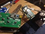 808.1 KB Views: 20