geezer88
Senior Member
Howdy All,
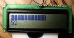
Here's a code snippet that uses custom characters to create a bar graph who's length is proportional to an input variable. This example uses a 2x16 display, so I've got the analog bar on line one and the input variable in digits on line two.
Since the lcd characters are created in a 5x8 matrix, there are 80 segments that make up the full scale bar. Unfortunately, the characters on a typical display are about one segment pitch spaced apart, so the bar is broken up by these spaces. I don't think there is anything to be done about that. I'd love to be proven wrong, though.
For my example, I use a touch input to get a variable to display. By pressing the touch pad gently to firmly I can get a reading from whatever the noise floor is to full scale. Noise is lowest by unplugging the programming cable FYI.
This was programmed on an 18M2, and the display is connected in four bit mode. Have fun.
tom
Code:
#rem    6/2/11
This bit of code displays individual segments as an analog display

#endrem

'* Pin Assignments  **************************************

	'LCD pin  6 = SE = c.6 = pin 15 MPU
	'LCD pin  4 = RS = c.7 = pin 16 MPU

	'LCD pin 11 = D4 = b.4 = pin 10 MPU
	'LCD pin 12 = D5 = b.5 = pin 11 MPU
	'LCD pin 13 = D6 = b.6 = pin 12 MPU
	'LCD pin 14 = D7 = b.7 = pin 13 MPU
	'touch input c.0	Used for a source of variable input

'* Symbols ************************************************

	symbol LcdSE = c.6			'strobe data into display
	symbol LcdRS = c.7			'set low for instruction, high for character entry

	symbol LcdByte = b0			'data sent to LCD routines
	symbol j = b1				'scratch byte
	symbol blocs = b2			'full 5x8 block character
	symbol segs = b3			'number of vertical segments in last char

	symbol huns = b4			'hundreds digit in bintoascii
	symbol tens = b5			'tens digit in bintoascii
	symbol ones = b6			'ones digit in bintoascii
	symbol in = b7				'input to be displayed - normally would come from some outside
								'world sensor or calculation


'* Main Routine *******************************************

	EEPROM 0, (0,0,0,0,0,0,0,0,16,16,16,16,16,16,16,16,24,24,24,24,24,24,24,24,28,28,28,28,28,28,28,28,30,30,30,30,30,30,30,30,31,31,31,31,31,31,31,31)

	'This list of data creates five user defined characters that are called to make partially filled blocks
	'0=no lines, 1=one line, 2=two lines, 3=three lines, 4=four lines

	gosub LCD_Init				'get lcd ready

	LcdByte = 64				'move to user memory slot 0
	gosub LCD_WrIns

	for j = 0 to 63				'write the data to LCD user memory
	read j, LcdByte
	gosub LCD_WrChr
	next j

	gosub LCD_init				're-initialize display - not sure this is needed
	lcdbyte = 128				'move to first line, first position
	gosub lcd_wrins

do								'for demo purpose this is simply looped continously

	touch c.0, j				'get some data for testing
	j = j / 3					'scale it a bit
	in = j max 80				'make sure full scale is not exceeded (overflow messes up stuff)

		blocs = j / 5			'number of whole blocks to print
		segs = j // 5			'remainder gives segments in last block
		j = blocs 				'reuse j for counter

		lcdbyte = 128			'move to begining of first line
		gosub lcd_wrins

	do until j = 0				'test first, then print blocks if needed

		lcdbyte = 255			'255 prints a solid block of 5x8
		gosub lcd_wrchr

		dec j

	loop

		if segs > 0 then		'print partial block if needed
			lcdbyte = segs
			gosub lcd_wrchr
		endif

		j = 17 - blocs  		'j is counter again, limiting number of characters to clear

	do until j = 0				'test first, then clear remaining spaces

		lcdbyte = 0				'prints a blank space
		gosub lcd_wrchr

		dec j

	loop

	lcdbyte = 192					'move to second line, first position
	gosub lcd_wrins

	bintoascii in, huns, tens, ones	'break down input number so it can be displayed

	lcdbyte = tens					'display tens
	gosub lcd_wrchr

	lcdbyte = ones					'display ones
	gosub lcd_wrchr

loop

end


'* Initialise LCD *****************************************

LCD_Init:

	'set relevant pins to output
	dirsb = %11110000
	dirsc = %11000000
	low LcdRS
	low LcdSE

	'wait for LCD to stabilise (>40ms after Vcc > 2.7V)
	pause 100

	'send 00110000 three times to initialise LCD by instruction
	outpinsb = %00110000
	pause 1
	pulsout c.6,1000
	pause 1
	pulsout c.6,1000
	pause 1
	pulsout c.6,1000
	pause 1

	outpinsb = %00100000	'set to 4 bit mode
	pause 1
	pulsout c.6,1000

	LcdByte = %00101000 'set interface
	pause 1
	gosub LCD_WrIns

	LcdByte = %00001100 'enable display, no cursor
	pause 1
	gosub LCD_WrIns

	LcdByte = %00000001 'clear and home cursor
	pause 1
	gosub LCD_WrIns

	LcdByte = %00000110 'set cursor direction: movement
	pause 1
	gosub LCD_WrIns

	return


'* Display Character On LCD *******************************

LCD_WrChr:

	high LcdRS	'set RS high (write data)
	pause 1

	outpinsb = LcdByte and %11110000
	pause 1
	pulsout LcdSE,1

	outpinsb = LcdByte * 16
	pause 1
	pulsout LcdSE,1

	return


'* Send Instruction to LCD ********************************

LCD_WrIns:

	low LcdRS	'set RS low (write instruction)
	pause 1

	outpinsb = LcdByte and %11110000
	pause 1
	pulsout LcdSE,1

	outpinsb = LcdByte * 16
	pause 1
	pulsout LcdSE,1

	return


'* Clear LCD **********************************************

LCD_Clear:

	LcdByte = 1
	pause 1
	gosub LCD_WrIns

	return


'* Home Cursor  *******************************************

LCD_Home:

	LcdByte = 128
	pause 1
	gosub LCD_WrIns

	return


'* Move To Line 1 *****************************************

LCD_Line1:

	LcdByte = 128
	pause 1
	gosub LCD_WrIns

	return


'* Move To Line 2 *****************************************

LCD_Line2:

	LcdByte = 192
	pause 1
	gosub LCD_WrIns

	return

'* Move To Line 3 *****************************************

LCD_Line3:

	LcdByte = 148
	pause 1
	gosub LCD_WrIns

	return


'* Move To Line 4 *****************************************

LCD_Line4:

	LcdByte = 212
	pause 1
	gosub LCD_WrIns

	return
Attachments
-
 51.2 KB Views: 228
")