LCD 20x4 and AXE134(18M2) driver 20X2 based for serial / i2c.

marks

Senior Member
Hi Haroen,
I'm almost tempted to say have you got good decoupling on that little thing.

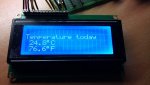
That will teach me I changed from a oled1602 to lcd204 for checking...
the driver will work for both but

post#33 should have worked but when programmed display would appear scrambled until powered off and on again.
the idea being to show what happens and try avoid using the serout pin to send too a display.

I think the SENDING example was a bad example and may have appeared scrambled it worked on the lcd ,
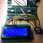
it was meant to show we could send 80 characters at once and how it wraps around the display line 1 then 3 then 2 then 4
checking it on the oled1602 it wasn't quit right it appears you can have 64 characters for each line controller not 40 as I expected.
I'm assuming this would be messy on a oled2004.
I will change this to basic 4 line addressing and send 20 characters I'm sure I've used that before on a oled.

Sorry for the run around !
 

Haroen

Member
Sorry guys, maybe I should post more info...
It is very hard for others to help if you do not post all the code you are using, do not show your hardware connection scheme, and do not detail how the fault manifests itself; whether the initial 'welcome' message is corrupted or only data sent from the controlling PICAXE is corrupted.
The overall schematic I used was seen in post #25.
I've not deviated from the good advise and sourcecode of members where they have already implemented the hardware connection scheme in the top-section of their code.
Sometimes swapping pins for the "serout c.1,n9600_16,..." -command to A.4 or lower baudrates done in this post also advised by members.

From the moment that the welcome message worked (#23) only serial communication between picaxe chips on display was scrambled.
It's time for advise from George Michael "A different Corner": marks his previous post,...
http://www.picaxeforum.co.uk/showthr...-DISPLAY/page2, post#20!
* In the first 20X2 chip his code displays nothing, there is something wrong with that chip!
* In the desoldered 20X2 chip his code worked to display correct welcome text: "marks......"! :D

Now the serialOut or Hi2cOut from a 28X2 (converted code instead of a 18M2 from marks) has to send to the 20X2 display driver.
Changed code lines for serialOut or Hi2cOut ...
Code:
#picaxe 28X2
SETFREQ EM32
But the display stays on welcome message after sending?
Why doesn't it receive serin or i2c?
Missing though is a picture of some srambled text now displayed like Abracadabra for me lol (That's some inner Harry Potter speaking).:D
ScrambledText 20X2 smd.jpg

Hi inglewoodpete,
If both marks' and my (inglewoodpete's) code don't work then it suggests you have a wiring fault (bad connection on one or more wires).
I agree, but can't find one. Therefore I now have expanded the Hippy post #29 "added pauses", with alfabet (a-z), numbers (0-9), frequently used characters (!?%-()>>+) and works great.
Does that mean that there is still a wiring fault? The overall schematic I used was seen in post #25 still applies.
Code:
#Picaxe 28X2
#No_Table
#No_Data

SETFREQ M8
Pause 3000

Do
  serout A.4,N9600,(254,128)   				'Command Line 1 Cursor Position
  Pause 1
  SerOut A.4, N9600, ("a")
  Pause 1
  SerOut A.4, N9600, ("b")
  Pause 1
  SerOut A.4, N9600, ("c")
  Pause 1
  SerOut A.4, N9600, ("d")
  Pause 1
  SerOut A.4, N9600, ("e")
  Pause 1
  SerOut A.4, N9600, ("f")
  Pause 1
  SerOut A.4, N9600, ("g")
  Pause 1
  SerOut A.4, N9600, ("h")
  Pause 1
  SerOut A.4, N9600, ("i")
  Pause 1
  SerOut A.4, N9600, ("j")
  Pause 1
  SerOut A.4, N9600, ("k")
  Pause 1
  SerOut A.4, N9600, ("l")
  Pause 1
  SerOut A.4, N9600, ("m")
  Pause 1
  SerOut A.4, N9600, ("n")
  Pause 1
  SerOut A.4, N9600, ("o")
  Pause 1
  SerOut A.4, N9600, ("p")
  Pause 1
  SerOut A.4, N9600, ("q")
  Pause 1
  SerOut A.4, N9600, ("r")
  Pause 1
  SerOut A.4, N9600, ("s")
  Pause 1
  SerOut A.4, N9600, ("t")
  Pause 1
  serout A.4,N9600,(254,192)   				'Command Line 2 Cursor Position
  Pause 1
  SerOut A.4, N9600, ("u")
  Pause 1
  SerOut A.4, N9600, ("v")
  Pause 1
  SerOut A.4, N9600, ("w")
  Pause 1
  SerOut A.4, N9600, ("x")
  Pause 1
  SerOut A.4, N9600, ("y")
  Pause 1
  SerOut A.4, N9600, ("z")
  Pause 1
  SerOut A.4, N9600, ("0")
  Pause 1
  serout A.4,N9600,(254,148)   				'Command Line 3 Cursor Position
  Pause 1
  SerOut A.4, N9600, ("1")
  Pause 1
  SerOut A.4, N9600, ("2")
  Pause 1
  SerOut A.4, N9600, ("3")
  Pause 1
  SerOut A.4, N9600, ("4")
  Pause 1
  SerOut A.4, N9600, ("5")
  Pause 1
  SerOut A.4, N9600, ("6")
  Pause 1
  SerOut A.4, N9600, ("7")
  Pause 1
  SerOut A.4, N9600, ("8")
  Pause 1
  SerOut A.4, N9600, ("9")
  Pause 1
  serout A.4,N9600,(254,212)   				'Command Line 4 Cursor Position
  Pause 1
  SerOut A.4, N9600, ("!")
  Pause 1
  SerOut A.4, N9600, ("?")
  Pause 1
  SerOut A.4, N9600, ("%")
  Pause 1
  SerOut A.4, N9600, ("&")
  Pause 1
  SerOut A.4, N9600, ("-")
  Pause 1
  SerOut A.4, N9600, ("(")
  Pause 1
  SerOut A.4, N9600, (")")
  Pause 1
  SerOut A.4, N9600, (">")
  Pause 1
  SerOut A.4, N9600, ("<")
  Pause 1
  SerOut A.4, N9600, ("+")
  Pause 3000
  serout A.4,N9600,(254,1): Pause 30   		'Command Line 4 Clear
  Pause 3000
Loop
Can you post the (modified) code for my version of the driver chip (or, if already posted, indicate which post it is in), and I'll have a deeper look at over the coming weekend.
Post #7
I will also need a link (URL) to a copy of your 4-row, 20-column LCD's datasheet to better understand the configuration and addressing of each character position.
I'll have to surf for that and hope to find it's data before the weekend. But you know Chinese not well documented products unlike PICAXE!:cool:
 

marks

Senior Member
the trouble with using a.4 you have to power off and on each time
looks like its working(not from the picture from what you said further on lol)
I think you already said your power pins of the 20x2 has a0.1uF cap
your also feeding your lcd(some reason I thought you had a oled)
through that small board you should really also have a 47uF cap for power decoupling within a few inches ?
what version is your 28x2 can it do m16 it will change the baud rate slightly but don't think thats a problem
 
Last edited:

hippy

Technical Support
Staff member
From the moment that the welcome message worked (#23) only serial communication between picaxe chips on display was scrambled.
I now have expanded the Hippy post #29 "added pauses", with alfabet (a-z), numbers (0-9), frequently used characters (!?%-()>>+) and works great.
It would seem that your LCD wiring is correct. So, between that working and what you have which does not work, what are the differences ?
 

inglewoodpete

Senior Member
From the moment that the welcome message worked (#23) only serial communication between picaxe chips on display was scrambled.

Missing though is a picture of some srambled text now displayed like Abracadabra for me lol (That's some inner Harry Potter speaking).:D

Hi inglewoodpete,

I agree, but can't find one. Therefore I now have expanded the Hippy post #29 "added pauses", with alfabet (a-z), numbers (0-9), frequently used characters (!?%-()>>+) and works great.
Does that mean that there is still a wiring fault? The overall schematic I used was seen in post #25 still applies.
Ok, since the 20X2 can write to the LCD properly when the data is sourced from within the LCD driver chip, that suggests that the PICAXE-to-LCD side is wired correctly. In the case of marks' code, as he has said the problem is the slow data handling capability of the bit-banged SerIn command.

If you are still trying to use my code as it stands, you need to send INVERTED serial data at 115,200 baud into the hSerial pin. Either that or change the hSerSetup command.
 

Haroen

Member
Hi Marks,
I've added 2x 0.1uF caps on both sides of the circuit and 1x 100uF.
Code from post#33 also displayed scrambled but changing symbols.
Version of my 28X2 is vB.1 and my "Picaxe development board axe091" version 2B can do m16.

Came to the idea to try this code on a picaxe 28X2 and it worked!
And without oscilloscope hooked to it!
I think that this way I can exclude the LCD+header and wires out of the equation.
I don't want to lose so many LCD driver pins when I would use a 28X2 though, so really want to know what I do wrong.
It would seem that your LCD wiring is correct. So, between that working and what you have which does not work, what are the differences ?
Remains:
  1. Serial communication is currupt somehow and I've to try solotion post #45, like inglewoodpete mentioned.
  2. Firmware 20X2 chip version, what is now the newest 20X2 chip version available?
  3. And what Firmware 20X2 chip version does Marks and Inglewoodpete use that worked for them?
  4. Why did the LCD driver code did work on the 28X2 in post #23? Is it still a software issue?
  5. I've yet to test if i2c is also working correct on a 28X2...

Thanks for the patients and help guys!
 
Last edited:

marks

Senior Member
Hi Hareon,

sometimes my posts arent as clear as they should be ! life can be busy and am suffering from last nights hangover

so you can rule out noise ( also you can plug the lcd into the breadboard to remove some noise from the 20x2 board.)

1. is worth trying I have also posted code for using Hser
( i believe it also self adjusts for baud differences and errors).

2. latest 20x2 c.3 and 40x2 b.3
(i,m unsuree if the 28x2 b.3 executes code faster than the 40x2 i dont have 1)

3. If I think versions are important i nearly always include them at the top of my posted code
because i've directed some to my my code snippet lately
I recented checked and corrected it worked with the latest versions i have.

4. 20x2 ver c.0 I eventually remembered from my own use .I used outpins because that firware had problems with letpins
( you seem to have damaged while doing external testing so that chip didnt work anymore.)

5. Hi2c can be harder to get working
I use fast (400) because it also has built in noise error correction unlike slow (100)
needs less buffer pauses works ds3232 and others.
other stuff while i think
i have posted working examples in the code snippets area N9600 , Hi2cFast , Hser ( perhaps you didnt find)
http://www.picaxeforum.co.uk/showthread.php?19474-Learning-to-Drive-an-LCD-DISPLAY/page5
(i usually do final tests at there highest speed which i think work well and post that because thats what i think will be tried)
if having problems try slower speeds be more generous with your pauses (pause 100)
as every one's set up can be different.

ive never seen 20x2 ver c.2
revision history suggests problems with N9600_8
so i wanted you to at least try N9600_16
Code:
Current 20X2 production firmware is version C.3

ISSUE -    	KBLED COMMAND DOES NOT WORK CORRECTLY
		The kbled command does not light the keyboard LEDs as expected.
		There is no workaround for this issue.

Previously resolved issues:

ISSUE -    	CORRECTED ISSUE WITH SHIFTIN AND SHIFTOUT IDLE HIGH MODES
		The xxxx_H 'idle high' modes of shiftin and shiftout do not operate as expected.
		To workaround this issue use the bit-busting routines described in manual part 2.	
		Fixed in vC.3

ISSUE -    	ISSUE WITH READREVISION FROM EXTERNAL I2C SLOT
		The readrevision command did not function correctly on programs in external i2c memory.
		Fixed in vC.3

ISSUE -    	MODIFIED FVR OPERATION SO NO LONGER RESET BY READADC COMMAND
		A readadc command would reset fvrsetup to 0.
		To workaround this issue reissue a fvrsetup command after the readadc command. 
		Fixed in vC.3

ISSUE -    	IMPROVED SERIN AND SEROUT BAUD RATE ACCURACY (9600_8)
		The following baud rate settings are not as accurate as would be expected for serin/serout commands
		: 9600 at 8MHz
		: 4800 at 4MHz
		: 19200 at 16MHz
		: 38400 at 32MHz
		To workaround this issue use the baud rate at a different setfreq frequency, e.g. instead of using
		serin pin,N9600_8,variable
                use 9600 at 16MHz instead e.g.
		setfreq m16: serin pin,N9600_16,variable : setfreq m8
		Fixed in vC.3

UPDATE -    	IMPROVED PULSOUT ACCURACY, INTERNAL INTERRUPTS NOW DISABLED DURING PULSOUT
		The pulsout accuracy has been improved, and internal interrupts are now suspended to improve accuracy.
		Updated in vC.3

ISSUE -    	USE OF PWMDIV ON DIFFERENT PWM CHANNEL NO LONGER RESETS OTHER PWM CHANNEL DIVIDERS
		Use of pwmdiv on a pwmout channel could cause the divider on a different channel to be reset to 1.
		Updated in vC.3

ISSUE -		CORRECTED ISSUE WITH SHIFTIN COMMAND
		The shiftin pin may not work correctly on certain pins.
		To workaround this issue make sure the (SDI) data in pin in C.3, C.4 or C.5
		Fixed in vC.2

ISSUE -		CORRECTED ISSUE WITH RUN COMMAND SOMETIMES NOT WORKING IF SERVO IS ACTIVE
		Run command may not activate quickly if active servo outputs in current program.
		To workaround this issue switch off all servos and add a small delay before the run command.
		Fixed in vC.2

ISSUE -		PERIPHERAL MODULES (HI2C, HSERIAL, HSPI, SRLATCH) NOW RESET AFTER NEW PROGRAM DOWNLOAD
		Some internal peripheral modules are not reset after a new program download.
		To workaround this issue either manually reset these modules or simply press the reset button.
		Fixed in vC.2

ISSUE -		TIMER3 CLEARED AFTER RESET
		Timer3 value is not cleared upon a (non power up) reset.
		To workaround this issue manually reset using tmr3setup command.
		Fixed in vC.2

ISSUE -		PAUSE WITHIN AN INTERRUPT CAN NO LONGER BE INTERUPTED AGAIN AND HENCE SHORTENED
		A pause within an interrupt command can be shortened if the interrupt condition is still true.		
		Fixed in vC.2

ISSUE -		CORRECTED ISSUE WITH FIRST BYTE AFTER A BREAK IN HSEROUT BEING IGNORED
		The first byte after a break within a hserout command is ignored.
		To workaround this issue add an extra dummy byte at the start of the hserout command.
		Fixed in vC.2

ISSUE -		CORRECTED ISSUE WITH SERIN TIMEOUT HALTING BACKGROUND TASKS
		Upon a timeout from a serin command background tasks such as timers and i2c can momentarily pause. 
		Fixed in vC.2

ISSUE -		CORRECTED ISSUE WITH HPWM FULL AND HALF MODE OPERATION
		HPWM modes do not work correctly.
		Workaround for PWMHALF mode
			Symbol PWMPOLARITY = PWMHHHH
			PokeSfr $B9, %00001111
			HPwm PWMHALF, PWMPOLARITY, 0, , 
			PeekSfr $BD, b0
			b0 = b0 | %10000000 | PWMPOLARITY 
			PokeSfr $BD, b0
		Workaround for PWMFULL_F mode
			Symbol PWMPOLARITY = PWMHHHH
			PokeSfr $B9, %00001111
			HPwm PWMFULL_F, PWMPOLARITY, 0, , 
			PeekSfr $BD, b0
			b0 = b0 | %01000000 | PWMPOLARITY 
			PokeSfr $BD, b0
		Workaround for 	PWMFULL_R mode
			Symbol PWMPOLARITY = PWMHHHH
			PokeSfr $B9, %00001111
			HPwm PWMFULL_R, PWMPOLARITY, 0, , 
			PeekSfr $BD, b0
			b0 = b0 | %11000000 | PWMPOLARITY 
			PokeSfr $BD, b0
		Fixed in vC.2

ISSUE -		CORRECTED ISSUE WITH SERVO COMMAND IN EXISTING PROGRAM PREVENTING DATA MEMORY AREA REPROGRAMMING CORRECTLY
		A servo command in the current program can cause a verification error when reprogramming with a new
		program (data program area only).
		Workaround 1 	- Add a '#no_data' directive to your program
		Workaround 2	- Start the programming with a hard reset (ie power on)
		Fixed in vC.1

ISSUE -		CORRECTED ISSUE WITH STRONG PULL-UP OPTION BIT AFTER OWIN/OWOUT COMMANDS
		The strong pull-up option after a owin/owout command does not work correctly with devices such as DS18B20
		due to incorrect timing tolerances.
		No workaround available.
		Fixed in vC.1

ISSUE -		CORRECTED ISSUE WITH SETTING Vref+ ON EXTERNAL ADC1
		Bit 14 of ADCSETUP does not correctly select the Vref+ as external ADC1.
		To workaround add 'pokesfr $22, 4' after the ADCSETUP command.
		(note also that Vref- is always fixed to 0V on all versions of the 20X2)
		Fixed in vC.1

ISSUE -	    	CORRECTED ISSUE WITH HSPISETUP COMMAND
		The hspisetup command does not automatically configure the pin B.7 as an output.
		To workaround the issue add an 'output B.7' command directly after the hspisetup command.
		Fixed in vC.1

ISSUE -		CORRECTED ISSUE WITH HARDWARE INTERRUPT EVENTS (E.G. HINT0, TIMER ETC) STOPPING HSPI COMMUNICATION
		HSPIIN / HSPIOUT commands can be erratically corrupted by other hardware interrupt events.
		To workaround this issue disable all hardware interrupt based events during HSPI communication.
		Fixed in vC.1

ISSUE -		CORRECTED ISSUE WITH SERVO COMMAND AT 32MHZ
		The servo command does not work at 32MHz
		To workaround this issue add a 'pokesfr 11,194' command after 'setfreq m32' 
		Fixed in vC.1

UPDATE -	MODIFIED SERVO COMMAND TO HELP REDUCE OCCASIONAL TWITCHING
		Updated in vC.1

ISSUE -		MODIFIED SEROUT TIMING FOR MORE RELIABLE OPERATION WITH AXE033 SERIAL LCD
		On #var within 'serout' commands the data may be sent to quickly for AXE033 to process.
		To workaround this issue use BINTOASCII instaed of #var
		Fixed in vC.1

ISSUE -	    	CORRECTED ISSUE WITH PLAY/TUNE/OWOUT/OWIN/READTEMP/READOWSN AFFECTING OTHER OUTPUTS
		The play and tune commands operate  but also incorrectly corrupt the value of up to two other output pins. 
		Two different workarounds are possible.
		Workaround 1 	- Use C,4, C.5 or C.6 for the piezo connection. These pins are not affected by the issue.
		Workaround 2	- Make sure the affected associated pins are configured as inputs rather than outputs so
				  these associated pins will then not be affected.
					Output	Affected Pins		Output	Affected pins
					B.0	A.0 AND B.1		C.0	C7
					B.1	B.0 AND B.2		C.1	B.3 AND C.7
					B.2	B.4 AND B.0		C.2	B.4 AND C.6
					B.3	C.3 AND B.1		C.3	OK TO USE
					B.4	C.4 AND B.2		C.4	OK TO USE
					B.5	B.6 AND B.4		C.5	OK TO USE
					B.6	B.7 AND B.5		C.6	N/A
					B.7	C.0 AND B.6		C.7	C4
		Fixed in vC.1
I was asking for the version 28x2 so i could look at history but cant find the old one
I believe if you the old pe5.5 installed it can be found in the files somewhere unfortunately ive lost a lot of work
and reformated to use w10 now.
the manual1 isnt clear that you can use m16 so didnt know if you tried it ?
but other docs show x2' can use m16
Code:
Current PICAXE-28X2 production firmware is version B.3

Known issues:

ISSUE -    	SHIFTIN/SHIFTOUT IDLE HIGH MODES DO NOT WORK CORRECTLY
		The xxxx_H 'idle high' modes of shiftin and shiftout do not operate as expected.
		To workaround this issue use the bit-busting routines described in manual part 2.

ISSUE -    	KBLED COMMAND DOES NOT WORK CORRECTLY
		The kbled command does not light the keyboard LEDs as expected.
		There is no workaround for this issue.


Previously resolved issues:

B.3 was the first release of the PICAXE-28X2 (PIC18F25K22).
Previous firmware versions were the discontinued PICAXE-28X2-5V (PIC18F2520) part.
i think i need a drink! lol
 

inglewoodpete

Senior Member
My code worked with 20X2 Firmware Version C.2 (C.0 had problems).

(i,m unsuree if the 28x2 b.3 executes code faster than the 40x2 i dont have 1)
28X2 and 40X2 are practically identical. The silicon is the same - the 40-pin chip just has more pins. I imagine the PICAXE firmware is identical too.
 

Haroen

Member
i have posted working examples in the code snippets area N9600 , Hi2cFast , Hser ( perhaps you didnt find)
http://www.picaxeforum.co.uk/showthread.php?19474-Learning-to-Drive-an-LCD-DISPLAY/page5
I've tried everyones (H)serial code without result.

revision history suggests problems with N9600_8
so i wanted you to at least try N9600_16
This I will try for all available codes and let you know

Marks, where did you find the picaxe version history?
I think it's wise to keep a listing for myself of all latest version of the picaxe family.
Version 20x2 c.3 will do the job for me like it did for you I think...
I never had to check the Picaxe firmware version before.

My code worked with 20X2 Firmware Version C.2 (C.0 had problems).
Good to know that there can be a difference for this kind of code like it was with Marks ("...outpins because that firmware had problems with letpins").
Because you also have the same firmware version I will try your code again on a new 20X2 vC.2 smd just to be certain.

This is the 20x4 display link where all info is both on "ProductDetails" and also the "Reviews" tab:
http://www.banggood.com/IIC-I2C-2004-204-20-x-4-Character-LCD-Display-Module-Blue-p-908616.html


( Perfect remedy: Last nights hangover and then need a drink! lol :cool: )
 

inglewoodpete

Senior Member
Because you also have the same firmware version I will try your code again on a new 20X2 vC.2 smd just to be certain.
Remember: there are two differences between your setup and mine. Yours is a 20 x 4 LCD display: mine was an OLED and only 16 x 2 rows. Please post the code you are trying to use.
 

hippy

Technical Support
Staff member
I've tried everyones (H)serial code without result.
"No result" is not very informative; exact details as to what works and what does not would help. For example, does the initial welcome display show without corruption, is data from the sending PICAXE not appearing, or appearing corrupted, will help identify where the problem lies.

If there is not an issue with your hardware and circuit, then the issue may be with the way you are trying to communicate and test your hardware, and perhaps the software from others you are trying expects hardware other than how you have it.

Things can get very confusing and hard to keep track of when dealing with multiple hardware and software configurations so it may be best to just ignore other code and concentrate on what you have as your own code and hardware.

In that respect it would be well worth providing circuit diagrams and code again so we can see exactly where you are at this moment in time. The easier you can make it for others to help you the easier it will be for others to help.

It is very easy to go off in all directions hoping something else will work but it is equally easy to get lost as to where the problem is or lose focus on the issue which needs to be solved.

So just stick to getting one hardware platform working without worrying that some other hardware platform may not be working either, same too for your software without worrying about whether other software works or not.

The most important information you can provide is whether your hardware and software puts the welcome message up on the display without corruption or not. If that works then the issue is less likely to be with your hardware than with your software or the testing software.
 

inglewoodpete

Senior Member
This is the 20x4 display link where all info is both on "ProductDetails" and also the "Reviews" tab:
http://www.banggood.com/IIC-I2C-2004-204-20-x-4-Character-LCD-Display-Module-Blue-p-908616.html
Thanks for posting details of your LCD hardware. I wish you had done that earlier. That module already has an i2c 'daughter board' interface attached to it.

My code is for a PICAXE 20X2-driven daughter board. Goodness knows how you have your version of my hardware/software arranged but it's not going to work.
 

hippy

Technical Support
Staff member
Thanks for posting details of your LCD hardware. I wish you had done that earlier. That module already has an i2c 'daughter board' interface attached to it.
That was my initial thought but from earlier posts it appears Haroen has removed the I2C daughter board and is using it in parallel mode or is actually using something else.
 

marks

Senior Member
Hi Haroen ,
I would try using a different picaxe to send to your 20x2driver to achieve better performance @ 9600.
with the 20x2 c.2 may be ok as ive used c.0 c.1 and c.3 but only tested hser with c.3

a driver has to run fast enough to update the display usually atleast (minimum)
M16 required for N2400
M32 required for N4800
M64 required for N9600 (between bytes)

Also try sending N4800 from your picaxe(actually this will not help much if you have to reduce driver to M32)
(28x2 ver B.1) history.
originaly this firmware may have been tested sending just a few bytes and buffering as it was normal to use this way.
The way I have written my code needs more time.
you mentioned it was working post#42 at m8 N9600 single characters with a pause1 (this is still quick).
it meens the baudrate is ok the pause is just giving us more time between bytes.(a longer stop bit)

If you look at the next ver B.2 improvements seem to have been made for use with the axe033 and hser
this may be why i've had better success with a more mature firmware.(using the latest silicon microchip also make improvements & corrections)
so its probaly easiest to use the latest chips like I have. Some of my code snippets show min pauses at highest speeds achieved.
I also have good decoupling on my boards this also helps you achieve better results with clean signals with little noise.

attachment has firmware file from PE5.5 showing history for the various (older)picaxe chips.
history for new chips are from the web (picaxe store)
 

Attachments

Last edited:

hippy

Technical Support
Staff member
As far as I can tell there should be no issues in creating a high-speed LCD driver using any PICAXE X2 chip no matter what its firmware version.

If there are any issues relating to specific firmware they would be implementation issues and could almost certainly be worked around by using alternative code which avoids those issues.

If there are any baud rate issues they can be ignored for now by starting with a low baud rate and getting the code to work with those baud rates. Baud rates can then be increased and any issues can be dealt with if they do arise.

While those things may be relevant to the circumstances at hand I think they are largely 'red herrings'. That Haroen's own and no one else's code works suggests a more fundamental problem.

I think it is probably something simple and fairly easy to identify if we had the information required to resolve that and use the right approach to fault finding.

The best way I can see to have done this, what I would do, and what I would guess most people writing high-speed drivers will have done is -

1) Detail the hardware
2) Start at default operating speeds, start with 2400 baud
3) Get the welcome message displaying
4) Get a SERIN version working for character data
5) Get control codes working
6) Convert that to background serial, get that working
7) Increase operating speed and baud rate
8) Enhance the functionality as desired

Unfortunately straying from that path makes it less certain that things will work, will make it harder to debug and determine what may be wrong if they don't.
 

inglewoodpete

Senior Member
The best way I can see to have done this, what I would do, and what I would guess most people writing high-speed drivers will have done is -

1) Detail the hardware
2) Start at default operating speeds, start with 2400 baud
3) Get the welcome message displaying
4) Get a SERIN version working for character data
5) Get control codes working
6) Convert that to background serial, get that working
7) Increase operating speed and baud rate
8) Enhance the functionality as desired

Unfortunately straying from that path makes it less certain that things will work, will make it harder to debug and determine what may be wrong if they don't.
That project strategy is almost identical to what I used (and use on any project).

One other point when adapting someone else's code to your project - ones level of knowledge and experience in the ingredients of the project. It is one thing to replicate someone else's project and quite another to port code etc. to different hardware. Programming skills, hardware skills and fault-finding skills are all important.

When I embarked on the high-speed serial, i2c and mapped i2c project, I was already well versed in PICAXE-style background serial, PICAXE i2c slave configuration and had built and coded 4 previous LCD projects before embarking on the high-speed OLED project.

Having said that, I am still willing to help Haroen to get his project working but need accurate feedback with active involvement in the diagnosis of any faults as they arise. I can't do Haroen's testing and development work for him. I'm sure marks feels the same about supporting his solution.
 

marks

Senior Member
Hi Hareon,
yes it can be difficult just to get your own code to work at times
I find it easier when you've had some experience writing code to picaxe using the same version especially when push in it along a bit lol.
Code:
Hi Haroen ,
Testing your PICAXE 20x2 version C.2 with the terminal using PE 6.0.8.11

Use code from your post#36 and reprogram your picaxe20x2 driver.
afterwards the  display should slowly display message. (marks......) sorry couldn't resist lol

I noticed you must have flying programming leads!
move your flying lead FROM pin2(S.I) TO pin3(Rx)
your now ready to try commands using the Serial terminal.

Open Picaxe/Terminal
Check COM port: selections and Baud Rate (9600)

You can make use of the Transmit Buffer: at the bottom and enter some commands for testing your 20x2 Driver.
leave the Transmit Mode: Raw (Selected  which is default anyway)

254,1          (click on Send or hit enter) Display should CLEAR.

"hareon"       (enter) what you typed should appear

254,1          Clear screen

254,194        Cursor to line2 position3

"hareontest1"   So far So good (hopefully lol)

You can now test controlling an output
disconect your (S.O) flying lead and conect a LED with suitable in series resistor for testing LED should be off as OUTPUT is low.

254,$21        Turn ON (high)

254,$20        Turn OFF (low)

end of test...
 

Haroen

Member
He guys, seems I have a lot to answer after my Car repair and inspection.
Although the thread seems more and more complex, it's not.
I was looking for a PICAXE serial(1 uP-pin only) driver for my chinese cheap 20x4 display to implement in my filament extrusion project.

The LCD link with only the display was deleted by Banggood and when ordering I had to switch to the Display with I2C for €2 more.
After a short failed test to get i2c working with the delivered i2C driver I removed it to also test it with serial communication.
(Eventually making their driver work later on is a work in progress.)

This thread was initialy meant to find already working (Serial/I2C) LCDdriver solutions where 3 jumped out with hardware and sourcecode available:
  1. PICAXE axe134(18M2 lcd driver) with 20X2 instead. Post #1.
  2. Driver for 20X2 lcd's by "Inglewoodpete". Post #1.
  3. Marks 20X2 LCDdriver. Post #11.
I've made a tiny pcb with Marks solution and want to do the same with Inglewoodpete's if testboard will work.
I welcome every suggested action of Marks his solution and Inglewoodpete his solution to try on their 2 setups I've made. That's the least I can do in my respect to them!
Sending each byte with a suitable delay was working and now I've unscrambled text displayed, :cool:
From that moment on hardware wasn't an issue anymore accept the one wire from a X2_serout-pin to 20X2_serin-pin with 1 pulldown resistor.
So sticking to one hardware and source was not my intention when starting the post although that would be indeed faster and simple, but...
Because I couldn't get my replication of those 3 project working on a 20X2_C.0 the "Firmware Revision History" became definitely an issue!
I would rather use a 20X2_vC.2 or vC.3 then to use an older 20X2_vC.0, vC.1 with a work-around a very old firmware bug.
I don't want to reinvent the wheel!

One other point when adapting someone else's code to your project - ones level of knowledge and experience in the ingredients of the project. It is one thing to replicate someone else's project and quite another to port code etc. to different hardware. Programming skills, hardware skills and fault-finding skills are all important.

When I embarked on the high-speed serial, i2c and mapped i2c project, I was already well versed in PICAXE-style background serial, PICAXE i2c slave configuration and had built and coded 4 previous LCD projects before embarking on the high-speed OLED project.
The picaxe is meant for 13 year young students missing those skills. My effort is to help make it work for everyone and learn in the process.

For "Firmware Revision History" see my next post.
 

Haroen

Member
Relevance of the "Firmware Revision History":
  • About overall "Project strategy" I had to add "Firmware Revision History" in the acquation!
    Initial testing of the LCDdriver I did was with a 20X2 vC.0 that has a lot of issues!
    In fact becomming aware of this, I will study all "Firmware Revision History" for all PICAXE chips I use to tackle problems faster.
    In a glance at the "Firmware Revision History" I found out a lot of errors I had in the past with other projects mentioned in the "Firmware Revision History"!
  • The Tab "Revision History" seems to be more specific in:
    http://www.picaxe.com/Hardware/PICAXE-Chips/PICAXE-20X2-microcontroller/
    Code:
    Revision History
    
    Current 20X2 production firmware is version C.3
    
    ISSUE -    	KBLED COMMAND DOES NOT WORK CORRECTLY
    		The kbled command does not light the keyboard LEDs as expected.
    		There is no workaround for this issue.
    
    Previously resolved issues:
    
    ISSUE -    	CORRECTED ISSUE WITH SHIFTIN AND SHIFTOUT IDLE HIGH MODES
    		The xxxx_H 'idle high' modes of shiftin and shiftout do not operate as expected.
    		To workaround this issue use the bit-busting routines described in manual part 2.	
    		Fixed in vC.3
    
    ISSUE -    	ISSUE WITH READREVISION FROM EXTERNAL I2C SLOT
    		The readrevision command did not function correctly on programs in external i2c memory.
    		Fixed in vC.3
    
    ISSUE -    	MODIFIED FVR OPERATION SO NO LONGER RESET BY READADC COMMAND
    		A readadc command would reset fvrsetup to 0.
    		To workaround this issue reissue a fvrsetup command after the readadc command. 
    		Fixed in vC.3
    
    ISSUE -    	IMPROVED SERIN AND SEROUT BAUD RATE ACCURACY (9600_8)
    		The following baud rate settings are not as accurate as would be expected for serin/serout commands
    		: 9600 at 8MHz
    		: 4800 at 4MHz
    		: 19200 at 16MHz
    		: 38400 at 32MHz
    		To workaround this issue use the baud rate at a different setfreq frequency, e.g. instead of using
    		serin pin,N9600_8,variable
                    use 9600 at 16MHz instead e.g.
    		setfreq m16: serin pin,N9600_16,variable : setfreq m8
    		Fixed in vC.3
    
    UPDATE -    	IMPROVED PULSOUT ACCURACY, INTERNAL INTERRUPTS NOW DISABLED DURING PULSOUT
    		The pulsout accuracy has been improved, and internal interrupts are now suspended to improve accuracy.
    		Updated in vC.3
    
    ISSUE -    	USE OF PWMDIV ON DIFFERENT PWM CHANNEL NO LONGER RESETS OTHER PWM CHANNEL DIVIDERS
    		Use of pwmdiv on a pwmout channel could cause the divider on a different channel to be reset to 1.
    		Updated in vC.3
    
    ISSUE -		CORRECTED ISSUE WITH SHIFTIN COMMAND
    		The shiftin pin may not work correctly on certain pins.
    		To workaround this issue make sure the (SDI) data in pin in C.3, C.4 or C.5
    		Fixed in vC.2
    
    ISSUE -		CORRECTED ISSUE WITH RUN COMMAND SOMETIMES NOT WORKING IF SERVO IS ACTIVE
    		Run command may not activate quickly if active servo outputs in current program.
    		To workaround this issue switch off all servos and add a small delay before the run command.
    		Fixed in vC.2
    
    ISSUE -		PERIPHERAL MODULES (HI2C, HSERIAL, HSPI, SRLATCH) NOW RESET AFTER NEW PROGRAM DOWNLOAD
    		Some internal peripheral modules are not reset after a new program download.
    		To workaround this issue either manually reset these modules or simply press the reset button.
    		Fixed in vC.2
    
    ISSUE -		TIMER3 CLEARED AFTER RESET
    		Timer3 value is not cleared upon a (non power up) reset.
    		To workaround this issue manually reset using tmr3setup command.
    		Fixed in vC.2
    
    ISSUE -		PAUSE WITHIN AN INTERRUPT CAN NO LONGER BE INTERUPTED AGAIN AND HENCE SHORTENED
    		A pause within an interrupt command can be shortened if the interrupt condition is still true.		
    		Fixed in vC.2
    
    ISSUE -		CORRECTED ISSUE WITH FIRST BYTE AFTER A BREAK IN HSEROUT BEING IGNORED
    		The first byte after a break within a hserout command is ignored.
    		To workaround this issue add an extra dummy byte at the start of the hserout command.
    		Fixed in vC.2
    
    ISSUE -		CORRECTED ISSUE WITH SERIN TIMEOUT HALTING BACKGROUND TASKS
    		Upon a timeout from a serin command background tasks such as timers and i2c can momentarily pause. 
    		Fixed in vC.2
    
    ISSUE -		CORRECTED ISSUE WITH HPWM FULL AND HALF MODE OPERATION
    		HPWM modes do not work correctly.
    		Workaround for PWMHALF mode
    			Symbol PWMPOLARITY = PWMHHHH
    			PokeSfr $B9, %00001111
    			HPwm PWMHALF, PWMPOLARITY, 0, , 
    			PeekSfr $BD, b0
    			b0 = b0 | %10000000 | PWMPOLARITY 
    			PokeSfr $BD, b0
    		Workaround for PWMFULL_F mode
    			Symbol PWMPOLARITY = PWMHHHH
    			PokeSfr $B9, %00001111
    			HPwm PWMFULL_F, PWMPOLARITY, 0, , 
    			PeekSfr $BD, b0
    			b0 = b0 | %01000000 | PWMPOLARITY 
    			PokeSfr $BD, b0
    		Workaround for 	PWMFULL_R mode
    			Symbol PWMPOLARITY = PWMHHHH
    			PokeSfr $B9, %00001111
    			HPwm PWMFULL_R, PWMPOLARITY, 0, , 
    			PeekSfr $BD, b0
    			b0 = b0 | %11000000 | PWMPOLARITY 
    			PokeSfr $BD, b0
    		Fixed in vC.2
    
    ISSUE -		CORRECTED ISSUE WITH SERVO COMMAND IN EXISTING PROGRAM PREVENTING DATA MEMORY AREA REPROGRAMMING CORRECTLY
    		A servo command in the current program can cause a verification error when reprogramming with a new
    		program (data program area only).
    		Workaround 1 	- Add a '#no_data' directive to your program
    		Workaround 2	- Start the programming with a hard reset (ie power on)
    		Fixed in vC.1
    
    ISSUE -		CORRECTED ISSUE WITH STRONG PULL-UP OPTION BIT AFTER OWIN/OWOUT COMMANDS
    		The strong pull-up option after a owin/owout command does not work correctly with devices such as DS18B20
    		due to incorrect timing tolerances.
    		No workaround available.
    		Fixed in vC.1
    
    ISSUE -		CORRECTED ISSUE WITH SETTING Vref+ ON EXTERNAL ADC1
    		Bit 14 of ADCSETUP does not correctly select the Vref+ as external ADC1.
    		To workaround add 'pokesfr $22, 4' after the ADCSETUP command.
    		(note also that Vref- is always fixed to 0V on all versions of the 20X2)
    		Fixed in vC.1
    
    ISSUE -	    	CORRECTED ISSUE WITH HSPISETUP COMMAND
    		The hspisetup command does not automatically configure the pin B.7 as an output.
    		To workaround the issue add an 'output B.7' command directly after the hspisetup command.
    		Fixed in vC.1
    
    ISSUE -		CORRECTED ISSUE WITH HARDWARE INTERRUPT EVENTS (E.G. HINT0, TIMER ETC) STOPPING HSPI COMMUNICATION
    		HSPIIN / HSPIOUT commands can be erratically corrupted by other hardware interrupt events.
    		To workaround this issue disable all hardware interrupt based events during HSPI communication.
    		Fixed in vC.1
    
    ISSUE -		CORRECTED ISSUE WITH SERVO COMMAND AT 32MHZ
    		The servo command does not work at 32MHz
    		To workaround this issue add a 'pokesfr 11,194' command after 'setfreq m32' 
    		Fixed in vC.1
    
    UPDATE -	MODIFIED SERVO COMMAND TO HELP REDUCE OCCASIONAL TWITCHING
    		Updated in vC.1
    
    ISSUE -		MODIFIED SEROUT TIMING FOR MORE RELIABLE OPERATION WITH AXE033 SERIAL LCD
    		On #var within 'serout' commands the data may be sent to quickly for AXE033 to process.
    		To workaround this issue use BINTOASCII instaed of #var
    		Fixed in vC.1
    
    ISSUE -	    	CORRECTED ISSUE WITH PLAY/TUNE/OWOUT/OWIN/READTEMP/READOWSN AFFECTING OTHER OUTPUTS
    		The play and tune commands operate  but also incorrectly corrupt the value of up to two other output pins. 
    		Two different workarounds are possible.
    		Workaround 1 	- Use C,4, C.5 or C.6 for the piezo connection. These pins are not affected by the issue.
    		Workaround 2	- Make sure the affected associated pins are configured as inputs rather than outputs so
    				  these associated pins will then not be affected.
    					Output	Affected Pins		Output	Affected pins
    					B.0	A.0 AND B.1		C.0	C7
    					B.1	B.0 AND B.2		C.1	B.3 AND C.7
    					B.2	B.4 AND B.0		C.2	B.4 AND C.6
    					B.3	C.3 AND B.1		C.3	OK TO USE
    					B.4	C.4 AND B.2		C.4	OK TO USE
    					B.5	B.6 AND B.4		C.5	OK TO USE
    					B.6	B.7 AND B.5		C.6	N/A
    					B.7	C.0 AND B.6		C.7	C4
    		Fixed in vC.1
  • Marks post #54 Attached Files "PICAXE FIRMWARE REVISION SUMMARY": "firmware.txt":
    "Note that some firmware revision codes are internal quality
    control markers, not modifications of the firmware. This is
    normally when the type of automated programmer used for
    programming the PICAXE bootstrap is changed."
    Does this mean that one 20X2_vC.2(mine, Haroen) can differ from another 20X2_vC.2(Marks, Inglewoodpete)?
  • Especcially these issues could then differ in chips:
    ISSUE - CORRECTED ISSUE WITH SERIN TIMEOUT HALTING BACKGROUND TASKS Fixed in vC.2
    ISSUE - MODIFIED SEROUT TIMING FOR MORE RELIABLE OPERATION WITH AXE033 SERIAL LCD Fixed in vC.1
    ISSUE - PERIPHERAL MODULES (HI2C, HSERIAL, HSPI, SRLATCH) NOW RESET AFTER NEW PROGRAM DOWNLOAD Fixed in vC.2
    ISSUE - CORRECTED ISSUE WITH FIRST BYTE AFTER A BREAK IN HSEROUT BEING IGNORED Fixed in vC.2
  • While testing I thought I was going CRAZY :confused: because the Baud_Frequency relation didn't work accordingly with the Serout table "BASIC COMMANDS" pdf page 217!
    ISSUE - IMPROVED SERIN AND SEROUT BAUD RATE ACCURACY (9600_8)
    The following baud rate settings are not as accurate as would be expected for serin/serout commands
    : 9600 at 8MHz
    : 4800 at 4MHz
    : 19200 at 16MHz
    : 38400 at 32MHz
    To workaround this issue use the baud rate at a different setfreq frequency, e.g. instead of using
    serin pin,N9600_8,variable
    use 9600 at 16MHz instead e.g.
    setfreq m16: serin pin,N9600_16,variable : setfreq m8
    Fixed in vC.3
    So apparently a new 20X2_vC.3 will work as I thought in my post #49:
    Version 20x2 c.3 will do the job for me like it did for you I think...
  • Now I also understand why Marks is asking me to try different baud_frequency combinations.:cool:
Code issues in my next post, cheers.
 

Haroen

Member
Remember: there are two differences between your setup and mine. Yours is a 20 x 4 LCD display: mine was an OLED and only 16 x 2 rows. Please post the code you are trying to use.
Hi Inglewoodpete,
Post #5 you suggested modification of your code and in post #7 i've uploaded the code but some remarks left in that post.


Code testing and results (also reply on Marks posts #54 and #57) see next post.

I NEED A BEER, OR TWO! :D
 
Last edited:

hippy

Technical Support
Staff member
Because I couldn't get my replication of those 3 project working on a 20X2_C.0 the "Firmware Revision History" became definitely an issue!
I would rather use a 20X2_vC.2 or vC.3 then to use an older 20X2_vC.0, vC.1 with a work-around a very old firmware bug.
I don't want to reinvent the wheel!.
I can appreciate not wanting to reinvent the wheel, but unless the wheel works it can often be quicker and easier reinventing it than trying to make what does exist work.

Even if the projects did not work because of the firmware version you have that does not mean your own project needs to use later or latest firmware. I personally cannot see any real problem with using older firmware versions even if that does require working round firmware bugs if that then works and the results are still good enough.

It seems better to me to resolve any firmware related issues than have to buy a new chip, and it is better to use older versions in projects where any firmware problems can be worked around than have them unusable or being problematic for other projects.

Yes, there are some firmware issues with early versions of 20X2 but none which would seem to affect what you are trying to do, so there should be no need for any workarounds for what you are doing.

In particular any issues with SERIN and SEROUT 9600 baud rate accuracy is worry over nothing. The software and functionality can be tested with any baud rate, and the final project won't even be using SERIN or SEROUT.

At one point it seemed everything that had been done was working and it would be just a few steps to having the project done, but then it veered off in a different direction with trying to get other code working which doesn't seem to work at all.
 

Haroen

Member
I did all the code testing and I have some amazing results.

I could now test the LCD driver board to the cheap Banggood display with a brand new 20X2_vC.3 as Drop-In-Replacement.
"Marks" his own circuit with his own code for separate Serial and separate I2C communication works great! :)
There was nothing wrong with my hardware other then the firmware version!
For Marks his 20X2 LCD driver code with combined Serial and I2C communication I couldn't find (out) a working "28X2 Testdrive 4bit to 20X2 Display Hi2C_Driver.bas"?
So just to be clear... everything else that Marks has send worked! Also Sending each byte without a delay was working and sending temperature variables in Marks his code.
Temperature Variable.jpg
Yes, there are some firmware issues with early versions of 20X2 but none which would seem to affect what you are trying to do, so there should be no need for any workarounds for what you are doing.

In particular any issues with SERIN and SEROUT 9600 baud rate accuracy is worry over nothing. The software and functionality can be tested with any baud rate, ...
I did the testing of the Baud_Frequency relation accordingly with the Serout table "BASIC COMMANDS" pdf page 217!
Five smd's and one thd 20X2_vC.2 all failed! I think timing issues!?
Sorry for not specifying more details because if some of the many combinations was working, results where a lot of bits and pieces of the sended text.

Relevance of the "Firmware Revision History":
Does this mean that one 20X2_vC.2(mine, Haroen) can differ from another 20X2_vC.2(Marks, Inglewoodpete)?
I've now archived all my PICAXE chips with the addition of the date of purchase.
20X2_vC.2
10-2011

Hippy, I think you're right when choosing between resolving any firmware related issues with workarounds or to buy a new chip.
When the problem is time consuming and when having multiple sourcecodes for different chips firmware versions and pin swapping is neccesary resulting in multiple routing pcb's then it's better to buy a new chip.
A PICAXE chip with particular firmware bugs is never unusable and can always be used for other projects.

I2CsipBanggood.jpg
Now the cheap Banggood LCD display works, it was delivered with a black I2C driver where the address is 0x27 or 0x3F.
Will the PICAXE chip succesfully drive this Banggood I2C driver?
 
Last edited:
Top