L293D chip doesn't appear to be working.

I'm trying to use a L293D chip to power tow motors but I can't get it to work, I've tested the motors separately and they both seem to work.
I've connected the chip using the following layout:
25264

And I'm trying to test the motors with this code:
25265

Any ideas on why it's not working?
Thanks
 

oracacle

Senior Member
Does your code run once? Also add pauses between commands to ensure they have time to respond. I will have a closer look later when I get home
 

erco

Senior Member
Your project is exactly the same as a Picaxe CHI035 board: https://picaxe.com/docs/chi035a.pdf, you should use that for reference. Hard to diagnose without seeing pics of your setup & soldering. Tiny motors, I hope? Sufficient battery power? Large wires? Looks like you are powering your Picaxe and motor from the same rails. Motors draw big current, dropping voltages cause brownouts & resets. Try separate supplies for Picaxe & motors to see if that helps.

Looks like both of the ENable lines are properly tied high. If I were you I'd remove the 18M2 from its socket and manually jumper the IN lines high & low to see if your L293D is working.

Per orcacle, add a long pause after setting your pins, you only show a snippet of your code. For instance:

low b.6: high b.7: pause 5000

Repeating, L293 and L298 are old school and very inefficient, they just heat up a lot. Any small modern H-bridge is far superior and easy to use. Per my other post, the Toshiba TB6612 is a great choice. Happy to send you one (or MX1508 orL9110S) to try if you're in the US, otherwise you can order one faster.

25269
 

Attachments

inglewoodpete

Senior Member
I'm having trouble reading your circuit diagram - bad choice of colours for my computer. It looks like the power for the motor comes from the PICAXE supply (I can't see a voltage regulator). So, assuming a 5.0 volt power source, the voltage after the diode would be around 4.3 volts. If a motor is trying to draw around 600mA at startup, the available voltage at the output of the L293D (according to the data sheet) would be 4.3 - 2.6 = 1.7 volts. If powered from 3 x AA cells, the voltage available could be lower.

Can you measure the voltage available at the output terminals of the L293D: (1) with no motor connected and (2) with the motor connected, and report back to us?
with the motors connected its reading 0 - 0.1 v not sure why but im going to see if adding a seperate battery to power the motors works
 
I tried providing seperate power to the chip, no success. I also tried upping my overall voltage this also didn't work. I then tried replacing the motor with and LED to see if it was reciving any voltage and i couldnt get the LED to light.
 

inglewoodpete

Senior Member
I can't see the detail in you circuit diagram. What value are you using for the input resistors for the L293D?

Also, what voltage are you reading on EACH output B.4, B.5, B.6 and B.7 with respect to Ground/0v?
 

Jack Burns

New Member
2.81 volts seems quite low.
What type of battery AAA, AA, C, D, or other (stabilised) power supply are you using? and what voltage is going to the PICAXE board?

I can't see any capacitors in your circuit, so the problem could be that when a motor attempts to start it causes a power dip which resets the PICAXE.
Try adding a 100nF and 100uF capacitor across the supply rails as close as possible to the PICAXE. See C1 & C2 in the schematic of post 5.

I notice you have 2 LEDs in your circuit, so it might be worth disconnecting both motors (or preferably removing the L293D if it's in a socket) and then running a simple test just to see if the LEDs flash alternatively. If that works, then you could try reconnecting the motors and re-insert the L293D.

Now insert your code from post 1 so that it's just before low LED1 and see if the LEDs still flash as before or whether you get erratic behaviour due to the motors trying to start.

Code:
#picaxe 18m2
#no_data
symbol LED1 = C.0
symbol LED2 = C.1

low LED1
high LED2

do
  pause 2000
  toggle LED1
  toggle LED2
loop
 

neiltechspec

Senior Member
Where did you get your L239 from, wasn't a well known auction site was it, if so it's more than likely a fake.

Been there, got that T shirt !.
 
2.81 volts seems quite low.
What type of battery AAA, AA, C, D, or other (stabilised) power supply are you using? and what voltage is going to the PICAXE board?

I can't see any capacitors in your circuit, so the problem could be that when a motor attempts to start it causes a power dip which resets the PICAXE.
Try adding a 100nF and 100uF capacitor across the supply rails as close as possible to the PICAXE. See C1 & C2 in the schematic of post 5.

I notice you have 2 LEDs in your circuit, so it might be worth disconnecting both motors (or preferably removing the L293D if it's in a socket) and then running a simple test just to see if the LEDs flash alternatively. If that works, then you could try reconnecting the motors and re-insert the L293D.

Now insert your code from post 1 so that it's just before low LED1 and see if the LEDs still flash as before or whether you get erratic behaviour due to the motors trying to start.

Code:
#picaxe 18m2
#no_data
symbol LED1 = C.0
symbol LED2 = C.1

low LED1
high LED2

do
  pause 2000
  toggle LED1
  toggle LED2
loop
I'll test that code when I can, thanks. I'm using two AA batteries and I added capacitors to the motors , I've also tried using four AA batteries but that doesn't seem to work either.
 

AllyCat

Senior Member
Hi,

All was explained by IWP in #6 :
I'm having trouble reading your circuit diagram [he's not the only one :( 
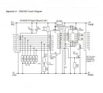
] ........ assuming a 5.0 volt power source, the voltage after the diode would be around 4.3 volts. If a motor is trying to draw around 600mA at startup, the available voltage at the output of the L293D (according to the data sheet) would be 4.3 - 2.6 = 1.7 volts. If powered from 3 x AA cells, the voltage available could be lower.
I'm using two AA batteries ,...
So how did you expect it to work? Two fresh alkaline AAs will deliver 3.0 volts at best, but less if they have been used previously and/or when loaded by a motor. Or two Rechargeable cells (NiMH) would give no more than 2.5 volts. So I'd expect there to be no useful voltage at all available across the motors. :(

Even 4 x AAs might struggle with that (unidentifiable type number) diode in series with the (L293D) supply rail; what is it supposed to do? Typically that circuit needs four cells wired directly to the L293D (i.e. so that it receives around 6 volts), but we've not been given any details about "the motors". Usually the diode would be connected in series with only the PICaxe (to keep its supply rail at a safer level). Then perhaps we could start a sensible discussion about why it "doesn't seem to work".

Cheers, Alan.
 

erco

Senior Member
Congrats! Could be the full moon or coriolis...

Start wiggling wires to look for intermittents. :)
 
Top