Koi Pond protector

the old fart

Senior Member
Hi Guys,

I have 3 electronic beams around my Koi Pond. The idea is that if any of the beams are broken, ie by a heron, then a water spray starts up to scare off the heron.
The water spray is from a pump mounted near the surface.

The system is working, using stripboard and relays, but I want to 'PIC' it.

I also have auto fill using another PIC, but thats another project.


I have programmed this to Picaxe 20m2.

Code:
 ; pond beam control
; Picaxe-20M2

; input
;0 stop spray
;1 beam 1
;2 beam 2
;3 beam 3
;4 dil 1 overide beam1
;5 dil 2 overide beam2
;6 dil 3 overide beam3
;7 dil 4 stop buzz


;output
;o
;1 timed relay delay off 24vdc
;2 timed relay delay off 24vdc
;3 relay 24vdc
;4 relay 24vdc
;5 buzzer 24vdc
;6 buzzer 24vdc
;7 watchdog 4vdc
 

;inputs

symbol nospray = b0 ; disable spray
symbol beam1 = b1 ;beam1 good
symbol beam2 = b2 ;beam2 good
symbol beam3 = b3 ;beam3 good
symbol switch1 = b4 ;overide beam1
symbol switch2 = b5 ;overide beam2
symbol switch3 = b6 ;overide beam3
symbol nobuzz = b7  ;disable buzzer

;outputs
symbol drelay = b16
symbol relay = b17
symbol buzzer = b18


start:

main:

if pin0=1 then let nospray=1:else:nospray=0:endif
if pin1=1 then let beam1=1: else: beam1=0:endif
if pin2=1 then let beam2=1: else: beam2=0:endif
if pin3=1 then let beam3=1: else: beam3=0:endif
if pin4=1 then let switch1=1:else:switch1=0:endif
if pin5=1 then let switch2=1:else:switch2=0:endif
if pin6=1 then let switch3=1:else:switch3=0:endif
if pin7=1 then let nobuzz=1:else:nobuzz=0:endif


if drelay=1 then high 1,2:else:low 1,2:endif ; output 1 and 2 linked
if relay=1 then high 4,3: else: low 4,3: endif ;output 3 and 4 linked
if buzzer=1 and nobuzz=0 then high 6,5: else: low 6,5: endif ;output 5 and 6 linked

goto main


start1:

;watchdog

main1:

high 7
pause 300
low 7
pause 300

goto main1

start2:

main2:

if buzzer=0 or nospray=1 then goto end3

drelay=1
pause 7000
goto main2
end3:
drelay=0
goto main2


start3:

main3:


lab1:
    if beam1=1 then lab3
    if switch1=1 then lab3
    
lab6:        
    let relay=0    
    let buzzer=1
    goto lab1
    
lab3:    
    if beam2=1 then lab4
    if switch2=1 then lab4
    goto lab6
    
lab4:
    if beam3=1 then lab5
    if switch3=1 then lab5
    goto lab6
    
lab5:
    let relay=1
    let buzzer=0
    goto lab1        

goto main3


I have 2 questions.

1/ is there a better way to transfer inputs 0-7 directly into b0-b7?

2/ main3: program I tried was: if (beam1=1 or switch1=1) and (beam2=1 or switch2=1) and (beam3=1 or switch3=1) then relay=1:else:relay=0:endif
is this possible as a single line command?


Cheers

Dave
 

eclectic

Moderator
Welcome to the Forum.

Can you give us more details about the
"beams" and also provide a schematic please?

e

I've changed your quotes to code
 

AllyCat

Senior Member
Hi Dave,

Welcome to the forum.

1/ If the inputs are all binary (logic) levels then you can read the whole port with one instruction. Then use bit variables in the conditional tests.

2/ You can't use brackets with a 20M2 (nor currently any PICaxe, despite what the manual says). However, you can link simple expressions with logical operators, but need to be very careful about the sequence of the operations (AFAIK always left to right).

For example the following seems ok in the simulator:
Code:
do
	b0 = pinsc				; Must use b0 to read bits 0 - 7
	if bit0 = 0 then gosub dosomething	; Pin c.0
	if bit1 = 1 then gosub dosomething	; Pin c.1
	if bit2 = 0 and bit3 = 1 then exit	; Pins c.2 and c.3
loop
	end

dosomething:
	return
Cheers, Alan.
 

the old fart

Senior Member
Welcome to the Forum.

Can you give us more details about the
"beams" and also provide a schematic please?

e

I've changed your quotes to code

Double Beams Outdoor 30m Black Active Infrared Detector

purchased off ebay.

30M was overkill, actual distance is 5M. had to turn down the transmitter voltage to 5v.
supply voltage is 14-24vdc, I run the receivers at 24vdc.
set of changeover contacts in each receiver.

each receiver comes back to PIC input 1,2,3
input 4,5,6 allow me to switch off individual beams if plants start obstructing beams.

outputs 1,2 go to a 24vdc relay, could just use output 1. this relay operates a 230vac pond pump that sprays over the surface of the pond.
if beam trips then pump runs for around 7 seconds, even if beam resets.

Have seen pigeons trip the sensors.

wiring is 2core 0.5mm.

Dave
 

the old fart

Senior Member
Hi Dave,

Welcome to the forum.

1/ If the inputs are all binary (logic) levels then you can read the whole port with one instruction. Then use bit variables in the conditional tests.

2/ You can't use brackets with a 20M2 (nor currently any PICaxe, despite what the manual says). However, you can link simple expressions with logical operators, but need to be very careful about the sequence of the operations (AFAIK always left to right).

For example the following seems ok in the simulator:
Code:
do
	b0 = pinsc				; Must use b0 to read bits 0 - 7
	if bit0 = 0 then gosub dosomething	; Pin c.0
	if bit1 = 1 then gosub dosomething	; Pin c.1
	if bit2 = 0 and bit3 = 1 then exit	; Pins c.2 and c.3
loop
	end

dosomething:
	return
Cheers, Alan.


Thanks Alan,

I'll experiment tomorrow.

I used to program industrial computers years back and service the electronics, so logistics is second nature.

Dave
 

sedeap

Senior Member
Hi Dave:

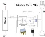
Maybe you want use a SSR style interface to get rid of those relays for 220v

MOCDriverDiag.JPG

C.U. Pals
:cool:
 

the old fart

Senior Member
If what you got works then why change, but should you want to, a SSR for AC is dirt cheap and connects direct to the picaxe.

Heres a link to what one is.

http://www.ebay.com.au/itm/280776557335?ssPageName=STRK:MEWAX:IT&_trksid=p3984.m1438.l2649#ht_4203wt_1153


Hi,
The pumps are controlled by SSR. its only the control circuit that uses the relays, which can be replaced with the PIC.


I did use a small SSR to control the pond fill, until it developed an internal fault and tried to sent 230v into the 24vdc control circuit.


Another question: could the 'Touch' function be used to detect water level?
I currently use 2 4mm stainless probes on a 5vdc sensing circuit.


Dave
 

Paix

Senior Member
I see Dave that you are qualifying to run for Australian politics . . . I used to supply potatoes, boots and hard tack biscuits to army bods, so my logistics skills are OK too . . .

And I guess I can shove my humour where the repositories go . . . :) Welcome to the forum and I guess the pigeons are impressed by the water spray too. Sounds good.
 

the old fart

Senior Member
update

experimenting using the 'touch' command for water level controller.

probe is a single stainless rod inside a plastic pipe with small holes drilled in it, to let the water in.

found that when water is in contact with the probe, a reading of '0' is produce.

with probe uncovered, random readings between 25-255.

Dave
 

westaust55

Moderator
To my knowledge, the PICAXE touch sensors are intended to be covered by a dielectric layer and utilise a capacitive effect between a finger and the sensor.
Thus it may be worth trying to:
  1. coat the metal probe with a layer to provide a dielectric layer - maybe even a thin layer of plastic
  2. calibrate the touch sensor
this may provide a better and possibly somewhat linear range of values as the level of liquid around the probe varies. COuld take some trial and error to determine the best material for coating.

There has been some past discussion on the PICAXE forum about using the Touch sensor with other materials and there are example calibration programs posted.
 
Top