Hi Circuit,
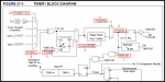
The particular feature of interest for this thread is that it's possible to "isolate" the T1Gate hardware from the Timer itself, giving some "free" logic gates/latches, whilst leaving the timer (and the PICaxe operating system) to work completely as normal. You may need to "get your hands dirty" delving into the "base" PIC data sheets (there are several useful timing diagrams for the T1Gate hardware) but the basic data is attached below. In principle it's only necessary to poke and peek one Special Function Register (T1GCON).
Conveniently, the "top" pins of the 08, 14 and 20 M2 chips are functionally identical, so T1G is Leg 3 on all three (or can be swapped to Leg 4 using the APFCON SFRegister). Alternatively, the on-chip comparator(s) (even on M2 devices) can be used as the Gate source, making up to another 6 pins a potential input source. The relevant (T1G) section of Timer 1 is attached below, with the SFR bit functions highlighted. The table describes the functions of the 8 bits which make up the T1GCON register.
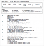
The most important feature is that if the Gate Enable bit (.7) is left clear, then the timer is unaffected, but the Gate circuit
continues to function and the "status" of the gate hardware can be read by two flags (.2 and .3). Other bits allow either the T1G pin or the comparators to be selected as source (.0 and .1) and the trigger polarity (.6) chosen. Either of the flags may be used to determine when an "event" has occurred. The Single Pulse Mode (.4) method is to set the GO/DONE bit (.3) when setting up the SFR and then poll the same flag to detect when a trigger has occurred. However, an alternative method is to setup the "Toggle" mode (.5) and then continually test for the latch (bit .2) being flipped from its previous state. The latter is potentially faster because there is no need to write to the SFR each time.
My own code is rather more complex (I'm using an on-chip Comparator as source) but the (untested) fundamental elements of the method are:
Code:
; Using M2 Gate Control Hardware to detect short pulses
; AllyCat June 2015

symbol T1GCON   = $19 			      ; Timer1 Gate Control Register (SFR=$19 for M2 devices)
symbol APFCON 	= $5D			;  Optional: Alternate Pin Function: T1GSEL = .3 (T1G on Leg 4 instead of Leg 3)

	 pokesfr T1GCON,$18 	 		     ; Trigger by a pulse on T1G pin
	do
		peeksfr T1GCON,b0
		if bit3 = 0 then			; /Done flag
;			do something
			pokesfr T1GCON,$18		; Reset the Go bit
		endif
	loop
Cheers, Alan.