Interfacing infra red photo reflectors into a PICAXE board with solenoid

Russel Lawrence

New Member
Hi everyone,

Im doing a uni project and some of you may already have read similar things from me but Im trying to get the circuitry correct so I can test (finally!)

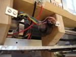
Basically what im trying to do is use two photo refelctors to count how fast two wheels are going and then if one is going 'x' times faster then turn on a solenoid to push against it and act as a brake.

The wheels are all set up and have holes around the circumference that these two reflectors sit next to. When a hole passes it nothing registors but when the surface passes it light is reflected back onto it and it counts a pulse (I hope!)

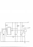
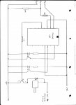
Im using the 18A chip that ive been given and Ive attached this diagram of how i THINK it chould be set up. This might be completely wrong as im rubbish with electronics but I was hoping for some advice/help
Thanks alot,
russel
(also hope Ive actually attched the file!)
 

Attachments

Russel Lawrence

New Member
Regarding the previous questions I am using the count command as the wheels are only rotating at approx 7Hz so I thought it would be able to cope with that.
I have looked at the manuals and that is what made me draw the circuit set-up that way but Im still not sure whether its right as there is no-one who can tell me where i am, but from what I can discern i think it is.
If its not is there a major error in it?
Thanks again
 

inglewoodpete

Senior Member
Russell,

As drawn, the circuit has a couple of problems.

It is best that the reset pin is 'pulled' high using a 4k7 resistor. The reset pin is used to reset the chip by pulling it to 0v: dangerous if there is no current limiting resistor to the 5v rail.

Your drawing does not show any pullup resistors on the collectors of the phototransistors. These are necessary to get a voltage that switches between (about) 0v and 5v as the light beams are interrupted by the disc.

Is the the transistor that is driving the solenoid an NPN or PNP? The symbol is incomplete. Perhaps you could indicate the model number.

When you say "rotating at approx 7Hz", do you mean (approx) 420 rpm? How many holes are there on the circumference of the discs?
 

MartinM57

Moderator
1. Picaxe has no 0V connection
2. Solenoid has only one connection
3. The optical couplers need another component in each of their circuits to work properly

...but as you're at Uni you should be able to work out the answer to 3. with a bit of digging...EDIT: or getting IWP to tell you :)
 

Russel Lawrence

New Member
Thanks,
the transistor is an NPN and the wheel is rotating at 420rpm with 9mm dia. holes drilled around the circumference at 105mm to their centres. Just realosed about the solenoid connection error and thanks for the 0V connection.
 

Russel Lawrence

New Member
Thanks for that, has helped alot. The codes for the transistors are BFY50 from SGS THOMSON microelectronics.
Ive attached my re-drawn circuit with your advice
 

MartinM57

Moderator
Getting better... :)

What do the resistors below the 4k7 pullups do? What value are they? Do you think you need them? What happens to the i/p voltage to the PICAXE when they are there?

What value resistors on the IR diodes? On the download resistor?

Why have you still not drawn the transistor symbol correctly? Are those the correct symbols for the receiver part of the optical coupler?

What part numbers are the PICAXE, optocouplers, diode and transistor?

Have a read of the datasheet for the BFY50 - a quick look shows an absolute max for Vceo at 35V for Ib = 0. Is that important in your circuit?


Simple checks for a circuit diagram:
- are all the symbols drawn correctly?
- are all the components labelled with their reference numbers (R1, R2, T1, D1 etc), and are the part numbers and/or values shown?
- is the purpose of every single component known and understood?
 
Last edited:

MartinM57

Moderator
...and on ICs it's normal to put the pin number outside the shape and the pin purpose (e.g. Serin) inside the shape - that way people can eyeball the connections without rushing off to a datasheet for the IC to see what each pin actually does (and to see whether you've connected the right ones, left important ones unconnected etc).
 
Last edited:

BrendanP

Senior Member
Could you use a hall effect sensor

I'm just thinking out loud here so to speak Russell. Im not sure how set in stone the features of your project are?

Could you use a hall effect sensor with a very small magnet on the wheel. The magnet passes by the sensor which is connected to the picaxe. You use the count or pulse in command and the picaxe counts the high- low cycles of the HES.

To actuate the braking mechanism you could use a linear actuator. You can find these on line, or you could make your own.

I remember someone posted a picture of a home brew unit.
Its just a piece of all thread being turned by a small motor. I think it would allow for far smoother ,finer brake control than a solenoid. true you would then have to make a motor controller or you could just buy one off the shelf like this one which works fine with picaxe.

http://www.trossenrobotics.com/store/p/5108-SyRen-25A-regenerative-motor-driver.aspx

or this one which is cheaper

http://www.parallax.com/Store/Accessories/MotorServoControllers/tabid/160/ProductID/64/List/0/Default.aspx?SortField=ProductName,ProductName

I suppose you could just pulse the solenoid on and off...

Look here there are variety of HES's that are easy to mount onto a frame or sheet metal etc.

http://au.mouser.com/catalog/637/1852.pdf

There are also a variety of magnets that are easy to mount.

Andrew Cowan posts on the forum regularly and is from London. He is into robotics which means he knows about electro mechanical stuff.

Why don't you PM him and see if you could set up a time when you could phone him or even meet with him? Having a hands on mentor will make your start into picaxe a lot easier.
 

eclectic

Moderator
@Russel

Have a look at this thread.
http://www.jeffree.co.uk/pages/revmaster.htm

Near the bottom of the page, look for
“Choosing a sensor and a measuring range”

Just above, and then below the paragraph title,
the author gives some interesting facts.

I genuinely don't know, but,
might you be better off with a different reflective sensor?

There are plenty of folks on the Forum who could advise.

e
 

Andrew Cowan

Senior Member
My robot has this kind of system to let the PICAXE know how fast the motor is going.

It uses slotted optocouplers and striped discs to create a waveform (is about 2V p-p and curvey). This goes into an op amp, which turns it into a 3V p-p digital signal. Ideally I would have used a rail to rail op amp, but that is all I had around.

This then goes into a transistor, which buffers it up to a standard 5V TTL digital signal. The PIC accepts this and works fine.

I had to experiment a vast amount with the pullup on the slotted opto, and with the protective resistor on the LED.

If you want, I could send you a PCB I designed for a two channel optocoupler setup to PICAXE interface (described above). You'd have to play with the resistor values for your particular relective LEDs/sensors, but it should be easy to get working.

Andrew

Edit: Where abouts are you in London?
 

Attachments

Last edited:

BCJKiwi

Senior Member
An alternative to both slotted and reflective photo interrupters are the switch versions which include transistor outputs eliminating the need for op amps etc.

The reflective types can be focused or unfocused. The focused versions have different focus distances.

So you need to know what you want/need/have.
 
Top