Interest in very simple but usable oscilloscope?

womai

Senior Member
Hi all,

as for sure many of you are aware by now, I like building test equipment including oscilloscopes. See the Picaxe scope at http://www.pdamusician.com/lcscope or the dsPIC oscilloscope at http://www.dpscope.com

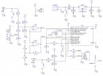
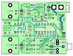
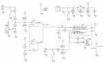
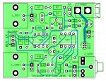
Right now I am playing with a much simpler design - not Picaxe based (I tried for quite a while but there just seems to be now way to get stable enough timing) but rather a PIC12F683 (same chip as the Picaxe 08M). Again it's a PC based scope. Preliminary schematic and board layout are attached to this post.

The idea is to minimize component count and cost while retaining a very simple-to-build design (e.g. no fine-pitch or surface mount components). It still has a frontend with input protection (large resistor, clamping diodes) and selectable gain/attenuation; input impedance is 1 MOhm so it can use any standard scope probe if desired (but works with just jumper cables as well - the BNC connectors are optional). Connection to the PC is through a serial cable with phono connector, so you could use the Picaxe download cable - further reducing cost. There is only a single channel, but it has a separate trigger input (for TTL/CMS signals, i.e. 0-5V) so you can trigger either on the measured signal or on a separate trigger.

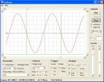
A basic prototype is already up and running on my desk. The PC software is also about 80% done. It should be able to do single-shot capture up to ~5000 samples/sec, and equivalent time sampling (for repetitive waveforms) up to 1 MSa/sec. That's good enough to look at signals up to ~100 kHz, so you could look e.g. at serial data strems, PWM, etc.

I am planning to make it an open design - i.e. schematic and firmware (HEX file and C source code) as well as the PC program freely available, so anybody can build his/her own. I estimate total component cost to be US$10 - US$30 for a one-off built on a stipboard, depending on what you already have in your drawer and what options you want (e.g. BNC connectors or none, and external power supply vs. 9V battery).

In addition I may also offer a pre-prgrammed microcontroller and the printed circuit board for people who e.g. don't have a PIC programmer or want a more professional looking board, but nobody will be forced to got that route. Still I'd like to hear how much interest there would be for that to judge if it is worth doing.

Wolfgang
 

Attachments

Last edited:

benmcl

New Member
What a great idea. This fits perfectly into my high school physics classroom where I have been having my students build their own equipment to run experiments, ie., breadboard a sensor circuit, program a picaxe, and download data into a laptop. As Stan and others have found, this is captivating to the students, as well as a rich learning experience. No need to spend $1000s per classroom for off-the-shelf equipment and modular sensors. (For full disclosure, I don't even have access to the $1000s I need to do otherwise.)
 

hippy

Technical Support
Staff member
I'm intrigued by the use of R5 and C2 - any hints :)

Out of intersest, accepting all the consequences of reduced bandwidth etc, how much more expesive would it be to replace the trigger and have two full channels ?

Could it even be simplified further, drop the op-amps and be, not much more than the PICmicro itself ?
 

womai

Senior Member
Ok, good, there seems to be some interest. Just don't expect me to finish everything in a day, I've got a busy life with a job and two kids :) Would love to see it getting used in a classroom setting.

The typo in the link to the Picaxe scope should be fixed now.

@hippy:

R5 and C2 are a low-pass filter for the PWM output - I use PWM to generate the trigger level and feed it into the negative side of the built-in comparator. Saves me from using an external DAC for the price of a somewhat less accurate trigger level.

There are lots of different trade-offs you can make. Since I am going to publish the firmware anybody can brew his/her own derivative if needed. So my design can be seen as a reference design meant as a baseline for your own efforts.

Right now it looks like I will change the microcontroller to a PIC16F684 - aka Picaxe 14M. That thing offers two comparators and has enough pins so I can attach an external resonator (16 or 20 MHz) - I'm running into some speed issues right now at 8 MHz internal clock.

Ditto with one channel vs. two channels. In real-time sampling mode I have to transfer data as it gets acquired - the uC does not have enough memory to hold a full record. The fastest I could get the (software) RS-232 to transmit reliably was 57200 baud, that allows up to 5000 samples/sec on one channel. Two channels will cut that in half. Above that I go to equivalent time sampling mode, i.e. acquire just one (or a few) samples per trigger event. With a 16F684 running at 20 MHz instead of 8 I hope I'll be able to increase the data rate to 115.2 kbaud (the fastest that standard RS-232 runs). With the additional pins and the additional comparator on the 16F684 I could get rid of the gain jumper (x1 and x10), and could also add a second channel. I'd use the quad MCP6024 op-amp instead of the dual MCP6022. Still it would mean a few additional components (resistors, trimmer) but that could be made optional.

As it is right now the frontend offers fixed offset so you can display positive as well as negative voltages, and total gain of roughly 0.1 and 1 (input divider is ~1:10, and op-amp provides 1:1 and 1:10 gain). That means you can measure voltages up to approx. +/-25V, or go down to 5mV resolution - i.e. cover a wide range. Also the input impedance is high and there is good overvoltage protection (to at least 200V DC, and more for short-term ESD) for the scope (and the attached computer!). That may be an important thing when you let kids handle that setup. Of course if you don't care about adjustable gain, protection, input impedance and ranges different from 0...5V then you could do away with the frontend, but I'm not sure I'd still call it a scope :) My goal is to produce something that's better than the quickly-slapped-together-and-left-lingering-in-a-half-usable-state microcontroller "scopes" you find on the internet.

Wolfgang
 
Last edited:

hippy

Technical Support
Staff member
Thanks. Two additional thoughts ...

1) Take a step back temporarily and design a high level protocol / specification for 'how it works'.

How data would be formatted and passed from micro to PC regardless of sample rate, bit-depth, number of channels, whether sampling or streaming, no matter what sampling rate, plus control the other way.

That would mean an open reference specification which everyone can work to whether building hardware or the PC-side Apps. People can pick and choose the $1 one-IC scope or the $5K scope, design the most impressive scopes based on the cheapest or best hardware, both sides can develop without understanding the other.

The scope can work with any compatible software on any OS, and people could use entirely different hardware based on other micro if they felt like it. That's got to be a good goal.

2) Consider an option of comms via an AXE027 cable as that allows far in excess of 115200 baud, nearer 1MBps.

That adds complexity into coding but, based on (1), if it can all fall down to the lowest common denominator you only have to make it feasible and define it, not actually have to do it. Everything automatically adopts to the lowest common denominator.
 

womai

Senior Member
Hippy,

thanks for your thoughts!

One common clash with designing a very open, flexible protocol is that it tends to add overhead. Not good if you want to wring every little bit of performance out of an underpowered little chip :) So I'll see what I can do but personally my preference is typically to put something together that actually works and is usable in reasonable time, rather than trying to create an "eierlegende Wollmilchsau" as we say in German (word-to-word translation would be "egg-laying wool-milk-sow", for something that is intended to do everything you could possibly wish for), but which typically never gets finished. As I indicated, I am just one person working on this with a small part of my time. I don't expect to get it perfect in the first round anyway and can always do a revision based on what I learn in the first round.

The baud-rate limit itself is caused by the microcontroller rather than the interface; those low-end devices don't have a hardware UART, thus I had to implement a bit-banged software UART (receive is done as a hardware interrupt-on-change for the start bit), and no matter how hard I tried and fiddled with the strobe timing I could not get the receive side reliable at 115 kbaud - it would work on some computer for some of the time, but not always; and I want to have something that is rock-solid so it also works when others build it with a different batch of uCs and connect it to a different computer... so even at 20 MHz clock I'm afraid 1 Mbaud is out of range.

Wolfgang
 

RobertN

Member
Womai,

Looks good!

QA couple comments. Adding a forward biased diode to the + power input would reduce the chances of a class room error taking out the scope.

I would like a low cost stand alone scope, a PC can get cumbersome away from a desk or work bench.
 

womai

Senior Member
Good idea with the protection diode. Will add that (if I don't forget overnight, that is :)

The problem with a standalone scope is - display, controls, enclosure all add a lot of cost. If it shall be usable in practice (rather than just a toy that makes you crazy having to press buttons a thousand times to change just one level) you need at least 2-3 rotary encoders and a few buttons; GLCDs with 128x64 pixels sell for ~US$15 in quantity but you need a larger microcontroller to drive it, and that screen size is still small. Going to 240x128 makes it more usable but doubles the price. Once you add it all up you've easily exceeded US$100 just in cost - and then add some markup for the effort, risk (got to stock much more components - otherwise people need to buy for one-offs, making it even more expensive), etc. My goal here is to stay below US$30 even if you buy the board and microcontroller from me, and largely make do with components most people already have in their drawer - still left to see if I can achieve that.

I have been considering adding a standalone option to my DPScope design, but haven't gone for it so far because of above reasons. Rigol sells their 50 MHz standalone scope for just over US$300 if you shop around a bit, and that thing's performance is orders of magnitude above what I could build for that price... so for lowest cost I tend to favor using the PC for control and display - after all, anybody living in a developed country and tinkering with electronics got one, and worst case an old laptop sells for less than you can build display and controls!

Just to avoid misunderstandings - this isn't meant to club down any idea that doesn't come from myself (I do try to avoid the "not invented here" syndrome :) but rather to explain why I tend to do something one way and not the other. I have been designing PC based scopes for a while now (almost 3 years) and naturally ran into many of the issues raised here. Of course nothing is set in stone and the more I learn the more options open up. Just got my Cypress PSOC eval kit - let's see what magic that can do. Microcontroller, programmable logic and programmable analog blocks all in one (DIP-28!) package sounds mightily promising to me!

Wolfgang
 
Last edited:

womai

Senior Member
new version

Ok, here is the redesign - now using the PIC16F684 (aka Picaxe 14M). I also added the protection diode at the power supply input. See attached schematic.

With the additional pins & functions I was able to improve functionality virtually without increasing cost or build complexity:
  • The scope can now switch between gain settings (x1 and x10) automatically (by using the appropriate ADC and comparator) - no more manual switching (jumper or toggle switch) - also reduces cost and component count.
  • Added an external 16 MHz resonator - doubles the execution speed and will hopefully allow me to increase the data rate to 115.2 kbaud and the maximum real-time sample rate to 10 kSa/sec.
  • Added a trigger output. This output will toggle whenever the scope receives a valid trigger. The idea is to use this signal to sync a second (or more) scope so one can capture more than one signal at a time. You'd simply hook up the trigger output of the first to the external trigger input of the second. That's almost as good as adding a second channel, and it keeps the base scope simple.
Feedback, suggestions, pointing out of mistakes in the schematic etc. is highly appreciated!

Wolfgang
 

Attachments

graynomad

Senior Member
This output will toggle whenever the scope receives a valid trigger
Do you really mean "toggle" or "pulse". A toggle will change state every trigger which will be difficult to trigger on with another device.
 

hippy

Technical Support
Staff member
Actually a toggle can be easy than a pulse for synchronisation as the receiver simply has to note the level has changed since last time. For a pulse there's often the added complexity of looking for the change, then making sure the pulse has gone low to avoid a subsequent false trigger.

It also avoids having to decide the length of a pulse. It won't help matters if a device is late for synchronising but the device will synchronise during any toggle high or low period even when late rather than miss a sync pulse completely.
 

graynomad

Senior Member
Fair enough, I just re-interpreted post #13 and see Wolfgang was referring to triggering another of the same devices.

I was thinking from the point of view of triggering something like a logic analyser, simple ones don't trigger on edges only levels.
 

womai

Senior Member
Actually I meant "pulse"; the second scope reacts on edges (not levels) anyway, like any typical scope, so you want e.g. a rising edge at each trigger even, not a rising on one and a falling on the next - that wouldn't work (or would need extra "sync" code in the second scope to handle the trigger input differently from normal scope operation).

Wolfgang
 

John West

Senior Member
As I stated in the past, Wolfgang - I'm very interested in such a scope to make available to young experimenters.

Years of experience playing with electronics circuits has shown beyond doubt that success in building circuits from scratch requires the ability to "see" what the little electrons are actually doing. Scopes are the way to do that. Multi-meters are handy tools, but a very poor scope substitute in a lot of cases.

While scopes are very useful they are one of the most expensive electronics tools for a hobbyist to acquire. A scope is the difference between a do-it-yourselfer and an electronics hobbyist. An open design and truly inexpensive PC based one with decent specs would be a great service to the hobbyist community and to electronics education in general. I'm all in favor of it.
______
BTW, Wolfgang - I'm still gathering up parts for the bds I got from you already. Almost done. A good thing too - because I have a bright-eyed 12 year-old boy I'm tutoring who is busy writing code for his PICAXE right now. As he builds everything from scratch, (no kit bds or sub-assemblies to speak of,) he will be needing some hardware debugging tools soon. A good little scope is a very good start.

An additional point in favor of such a scope - and something to keep in mind whist designing it - is that a truly inexpensive scope can be safely put in the hands of young students so they can directly learn from its use. I simply cannot afford to risk putting something like my TEK2467 or Philips PM3323 into the hands of someone who is just learning. (I shudder at the thought.) But for them to really learn well, that is exactly what needs to happen.

A truly inexpensive little scope module with easily repaired front end would be the ideal learning tool to put into small hands - and would save me nightmarish thoughts of smoke rolling from the seams of my beloved test equipment.
 

John West

Senior Member
And here is a screenshot of the PC software for the scope (and yes, that's a real waveform, no fake :)

Wolfgang
I don't know if the hardware and code are capable of it, but if it didn't hurt performance it would be very helpful to numerically display the frequency of sinusoidal waveform samples. I grow weary of counting divisions and doing the math - and kids find it to be a troublesome task without any great educational value.

Generally speaking - anything that can be done in software in the way of added features would be great. With software - after the work has once been done - it's forever free.

Open-source code for this project should really add to the possibilities. A pity I can't do C code - and everything needs to run too fast for the use of BASIC. Sigh.
 
Last edited:

cactusface

Senior Member
Pic Scope...

Hi Womai,
In the last 10 days or so I have brought 2 oscilloscopes from that well known shopping place on the net. One arrive dead on arrival, the other has a problem with the timebase circuit and drifts out of synch. My old scope also from the same market place, well the display just fades away, turn the intensity up, OK for another couple of minutes, etc, etc, repeat till there's nothing left.

So your little PicScope looks very interesting, A proper PCB I think would be best bet. Just a minute I have a Mac and no serial ports, but I do run windows on it and use a USB/Serial cable will that work???

Regards
Mel.
 

womai

Senior Member
UBS-to-serial converter cable should work without any issues - the design demands nothing special from the connection (i.e. no exotic baud rates and no break signals) that could cause compatibility problems.

Wolfgang
 

womai

Senior Member
I don't know if the hardware and code are capable of it, but if it didn't hurt performance it would be very helpful to numerically display the frequency of sinusoidal waveform samples. I grow weary of counting divisions and doing the math - and kids find it to be a troublesome task without any great educational value.
That may be a future addition. By the way, such automated measurements (not just frequency but quite a few others) are already implemented on my previous, more powerful design, the DPScope ( http://www.dpscope.com - see "Pictures" tab for a screenshot). That thing should still be inexpensive enough (and difficult to break anyway) to hand to a moderately experienced youngster, and offers quite a bit more performance.

Then again, starting out measuring things manually with cursors may not be such a bad start - the last thing I would want is somebody blindly trusting the numbers falling out from some automated routine! But I do agree that after a while moving cursors becomes a bit stale...

Wolfgang
 
Last edited:

papaof2

Senior Member
I've been hooked ;-) a $30 scope that fits in the laptop bag would be with me when I wanted to check something. For 80% of my PICAXE projects, the proposed specs would be adequate.

If the need for higher speed / greater range arises, I can fall back on the Tek 2247.

John
 

womai

Senior Member
For $30 you should be able to build the scope and put it in a small box. Only needs a few holes drilled (for 2x BNC, DB-9 or phono serial connector, on/off switch) so will be simple to do; the BNCs already provide the attachment for the board to the enclosure so the box size isn't critical at all.

Attached is the new schematic and layout with the 16F684. I was able to keep the board size the same as the 12F683 version - just 2.25 x 1.85 inches / 5.7 x 4.7 cm. The trace routing won't win me any awards - it was done in just late-night session. Some 16F684 samples are already in the mail from Microchip, once I got them I'll have to check out a few details of the design and then it's time to get some boards ordered.

Wolfgang
 

Attachments

Last edited:

graynomad

Senior Member
The trace routing won't win me any awards
Looks pretty good to me.

Two things, the pad annulars look a little small, are they OK for your board house?

Is that the standard Picaxe audio jack?, the data sheet I have shows the "ring" connection on pin 2, not 3. Although they do appear to be touching which would be OK.
 
Last edited:

womai

Senior Member
Thanks for the feedback!

Yes, it's the Picaxe audio jack. The two adjacent round holes are already explicitly connected with a trace (difficult to see in the jpg picture), so it doesn't matter to which one I route the trace from the resistor.

The annular rings would indeed be a bit small for a homebrew, self-etched PCB (where the holes aren't plated through), but are perfectly fine for any professional boardhouse (the holes are all plated through). I have had hundreds of DPScope and other boards manufactured with those dimensions, without any issue (it's actually on the coarse side for a "real" manufacturer). If I have them built in reasonable quantities (50 and up is reasonable) then the cost per board is so low that it wouldn't make any sense to roll your own anyway - board material, etchant etc. is going to cost the same or more, not counting the time and effort, and at the end you'd have a much inferior board... no silkscreen, no soldermask (a big help to avoid solder bridges during assembly!), no plated-through holes, no gold finish.

Wolfgang
 

graynomad

Senior Member
OK, just checking, better that than have an error after fab.

Have you tried any Chinese board houses, and if so can you recomend one? I need 8/8thou track/spacing and 16thou holes.
 

womai

Senior Member
I have been using PCBCart for a couple years now and am very satisfied. They are located in China. The guys there are knowledgeable, get back to your questions within a day or two, write excellent English, and their boards are good quality for little cost (e.g. gold plating is virtually the same price as solder reflow). Recently they even started offering assembly (although that is just getting started - I may have been their first customer for that :) and will procure the components for less than I can get them (although you need to supply any less common parts).

The only time I won't use them is for prototype boards, as their setup and shipping cost makes that a bit pricey: Even one piece of the smallest board comes in at ~US$100 once you include shipping and a lead time of 2-3 weeks, while I can two or three prototype boards for around $50 within the US with a lead time of ~1 week. But for anything exceeding maybe 10 boards the calculation is the opposite.

Wolfgang
 
Last edited:

graynomad

Senior Member
Glad you mentioned PCBcart, I've already been looking at them and figured I'd use them. I used to use another mob but they can't to the 8/8thou geometry.
 

womai

Senior Member
One thing I especially like about them - you can ask them questions and actually get meaningful answers quickly - really sets them apart from similar outfits. And they do customize things for you if you ask them. E.g. I needed a board to be broken apart into 3 pieces, and they came up with the necessary V-scorings themselves, I only had to check the sketch they sent me for correctness.

Wolfgang
 

womai

Senior Member
Short update: While waiting for the 16F684 samples to arrive (Microchip is taking their time...) I realized I had a (very old) 14M in my drawer that I never used - so I took it and made it a 16F684 again :) That allowed me to start breadboarding the design. Already discovered a serious oversight on my side - the PORTC pins don't have interrupt-on-change capability; this would have been fatal for the software serial receive which relies on this functionality.

Other than that, looking good so far. ADC and comparator don't seem to interfere with each other - so my idea for the trigger works. PWM (will be used for the trigger level) is already working as well. Right now I have the mockup running at 10 kSamples/sec in real-time sampling mode - meaning I can get useful displays of signals up to ~ 1 kHz. Blazingly fast - about 20 screen refreshs per second. Serial data rate is now 115.2 kbaud - timing resolution is no longer an issue since I run off a 20 MHz resonator.

Wolfgang
 

womai

Senior Member
For anybody wondering where this effort went: No, I didn't abandon it. Actually I have a rudimentary mockup of the scope working on my bench - including software. BUT when I got that far I also started playing around with the PIC18F2550 (that's the one that has USB built in). Not the first time I did that, but this time I was finally(!) able to successfully set up a USB HID connection driven in VB6. Hurraah! Such a great feeling seeing data being sent and received through USB, up to 64 KByte/sec (the theoretical maximum for a HID device), which is more than fast enough for my needs - after all, that's equivalent to ~640 kBaud for a RS-232 connection.

So where does that lead to? I decided that a simple scope based on a PIC18F2550 should cost virtually the same as the original (16F684 based) design, but would provide higher real-time sample rate (because I can bffer the data in the internal RAM), two full input channels instead of one, and be much more elegant (USB vs. legacy serial). There are even some cost savings because I can power it from the USB line instead of a separate battery or power supply. Still the initial effort is not lost - many of the tricks directly carry over (using the internal comparators for the trigger, generating the trigger level with PWM), also the analog frontend will stay the same (only doubled up). I started working on the sampling, so I guess I should have a rough proof-of-concept in the near future. My goal would be to have 50 kS/sec real-time sample rate for one channel (20 kS/sec if two channels are active), basically limited by the maximum acquisition speed of the internal ADC. And for repetitive signals at least 1-2 MSamples/sec in equivalent time sampling mode. Need to see what the analog bandwidth of the internal ADCs is (probably somewhere between 50 - 100 kHz).

Wolfgang
 

John West

Senior Member
Excellent! Keep at it, Wolfgang.

I've been following this thread closely, as I think your idea is great and the implementation just keeps getting better.

I think this little scope will be an indispensable counterpart to the PICAXE in operational speed and price for those on a tight budget (nearly all students) - and the perfect PICAXE troubleshooting tool, short of owning a good, fast, stand-alone storage scope.

For my own purposes I'd also like to see the serial port version implemented if it's not too much trouble, as I've a couple old laptops without USB ports that would make excellent dedicated scope boxes - but not much else.
 
Last edited:

lbenson

Senior Member
Another voice of encouragement. Better and better. I already find your previous two scopes useful, and the price and added features mean I can upgrade with comfort and move the older versions to places where I less frequently, but sometimes need a scope.
 

womai

Senior Member
Right now I am in feature-creep phase :) There's a good chance I can add basic signal generator functionality with minimal extra hardware (about $3 worth of components). That's the good news. The bad news is that such ideas will delay the final release date... ;)

Now to set expectations right, the new scope in question will have lower bandwidth and sample rate than the DPScope (limited by the lower execution speed of PIC18F vs. dsPIC, and the lower performance of the built-in ADCs - the dsPIC30F2020 can acquire two channels simultaneously within 1 usec, the PIC18F4550 only does one channel every ~10usec, and its analog bandwidth is also lower). On the upside I should be able to make the buffer 512 samples/channel deep (vs. the DPScope at 200 samples/channel), since the 18F has more RAM.

Wolfgang
 

womai

Senior Member
Yes, the feature creep has ended - I have a good idea what the instrument will/will not do. Hardware is still in the mockup stage - PIC18F4550 sitting on a development board. My life is currently very busy - have been on business travel almost every week for example - so not much progress. But once I get to it I expect that things should come togeter pretty fast since I will be able to re-use large portions of the DPScope PC software, I'll use the same PCB outline and same enclosure (reduces the mechanical work to almost zero), and I am much more experienced with DipTrace than I was when I did the DPScope (my first project using Diptrace to design the PCB).

Wolfgang
 

John West

Senior Member
I too am eager to see it come into being. This will indeed be an indispensable little tool for me. I already own several stand-alone 'scopes, but none I can pop in my jacket pocket, or afford to give away to a student to help with their PICAXE experiments and to actually "see" what all of those electrons are doing.

Even a simple, slow 'scope brings electron motion to life for a student or experimenter. Actually "seeing" what's going on is so important to understanding many facets of electronics. This little 'scope will likely expand some horizons.
 
Last edited:
Top