Hello PICsters,
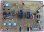
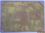
Yes I need a bit of help. But just a bit of history first. I decided some time ago to have a go at a PICAXE project from the ground up. Design, art work, etching the circuit board and programming the PICAXE. I also decided to try and build something that was not already posted all over the internet. And of course Amateur Radio related!
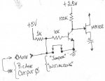
The project is a repeater controller board to control two VHF radios to be used as a repeater using a PICAXE 18X, a MC145436 DTMF decoder chip for remote control and programming and a LM358N in the audio section. This is just standard stuff as there are at least a half dozen of these designs on different Ham Radio operator’s web sites using a PIC16F84 chip but all seem to use .bin or .hex or .asm files. All those files are just to much for me. So hence the PICAXE! Also the curiosity to see if the PIAXE is up to the task.
The set up here is: Computer running a DTMF program, PC speakers with an earphone jack with the audio (DTMF tones) patched into the “Receive Audio” on my circuit board.
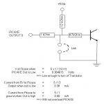
Problem #1…. I ran out of inputs! Lol. Haven’t we all heard that before! Correct me if I’m wrong, but the 18X has only 5 inputs? Actually, I didn’t realise this until after the board was etched and all parts were soldered on. The DTMF chip has 5 outputs. Four Data bits, D1, D2, D4, and D8 and a Data Valid pin to indicate that a valid DTMF tone has been received. I did use this pin to activate a LED and this is very helpful. But it really should have ALSO gone to an 18X input. I think it would make things easier. But the last input on the 18X was for the COR or CAS. This is an input from the receiving radio to tell the 18X that the squelch is open on the receiving radio and it is now receiving a signal. I think this should be solved by polling the inputs with something like:
If Input0 = 1 OR Input1 = 1 OR Input6 = 1 OR Input7 = 1 then GOTO GetDTMFTones
I think this solves this but maybe there is an easier way to detect that someone has pressed a button on the DTMF keypad and some or all the data pins are high on the DTMF chip.
Problem #2 (and a problem I can’t solve.)
First of all, I want to write the first three DTMF keypad presses to the EEPROM location and the next 3 keypad presses is the data I want to write to it. All in six consecutive key presses. So far, so good. Most of the data will either be the number 0, 1 or 2 to generate the call sign when it ID’s in Morse Code. Not the best way by no means but the easiest that I can think of for simplicity reasons. There’s no Hex to ASCII conversion charts required to program the 18X. All EEPROM memory locations 0 – 255 and the data to go in them are decimal. Right? But I would like to be able to change the tone for the speaker output which is a constant and set at 112, approx. 1000Hz. I think? So I would be required to write numbers three digits long for the data. It doesn’t matter to me if I have to write to EEPROM address 005 with three key presses of 0,0, and 5 or location 87 as 0, 8, and 7. This is fine. And for the data, it can be the same way too. The number 2 can be key presses 0,0, and 2. It doesn’t have to be just the button #2 only. Unless it’s easier to program. But I can’t figure it out.
As you can see in my not so clever code, When I write to EEPROM, b7 = b1 + b2 + b3, this just adds them up. It doesn’t make a 3 digit number!!! So the highest possible number from 0 – 9 is 27 for the memory location in EEPROM to write to and the largest number to be written to it, is also number 27. There is a bit of a work around. B7 = B1 * B2 *B3.
But this is cheap and nasty and takes away the “simplicity”. Also, possibly not all 0 – 255 EEPROM memory locations would be available? Could you write the number 250 to EEPROM location 250??? I’ve toyed around with this for two nights burning the midnight oil and I’m cryin’ for help!
Beware, all the mumbo jumbo in the code to change a DTMF key press for byte b0 from one number to another is due to the DTMF chip data bit D1 going to Input7 on the 18X. This generates a number 128 in the PICAXE. Or D8 going to Input0. This generates a number 1. etc. etc. It took me two evenings to figure that out! But it was a learning experience.
I’m sure you know what I’m after, it’s three consecutive key presses to equal one complete number. I’m sure you know what I mean.
Sorry for the huge post. Just trying to let you know exactly what I’m trying to accomplish.
Cheers,
The “HamRadioAddict”
Yes I need a bit of help. But just a bit of history first. I decided some time ago to have a go at a PICAXE project from the ground up. Design, art work, etching the circuit board and programming the PICAXE. I also decided to try and build something that was not already posted all over the internet. And of course Amateur Radio related!
The project is a repeater controller board to control two VHF radios to be used as a repeater using a PICAXE 18X, a MC145436 DTMF decoder chip for remote control and programming and a LM358N in the audio section. This is just standard stuff as there are at least a half dozen of these designs on different Ham Radio operator’s web sites using a PIC16F84 chip but all seem to use .bin or .hex or .asm files. All those files are just to much for me. So hence the PICAXE! Also the curiosity to see if the PIAXE is up to the task.
The set up here is: Computer running a DTMF program, PC speakers with an earphone jack with the audio (DTMF tones) patched into the “Receive Audio” on my circuit board.
Problem #1…. I ran out of inputs! Lol. Haven’t we all heard that before! Correct me if I’m wrong, but the 18X has only 5 inputs? Actually, I didn’t realise this until after the board was etched and all parts were soldered on. The DTMF chip has 5 outputs. Four Data bits, D1, D2, D4, and D8 and a Data Valid pin to indicate that a valid DTMF tone has been received. I did use this pin to activate a LED and this is very helpful. But it really should have ALSO gone to an 18X input. I think it would make things easier. But the last input on the 18X was for the COR or CAS. This is an input from the receiving radio to tell the 18X that the squelch is open on the receiving radio and it is now receiving a signal. I think this should be solved by polling the inputs with something like:
If Input0 = 1 OR Input1 = 1 OR Input6 = 1 OR Input7 = 1 then GOTO GetDTMFTones
I think this solves this but maybe there is an easier way to detect that someone has pressed a button on the DTMF keypad and some or all the data pins are high on the DTMF chip.
Problem #2 (and a problem I can’t solve.)
First of all, I want to write the first three DTMF keypad presses to the EEPROM location and the next 3 keypad presses is the data I want to write to it. All in six consecutive key presses. So far, so good. Most of the data will either be the number 0, 1 or 2 to generate the call sign when it ID’s in Morse Code. Not the best way by no means but the easiest that I can think of for simplicity reasons. There’s no Hex to ASCII conversion charts required to program the 18X. All EEPROM memory locations 0 – 255 and the data to go in them are decimal. Right? But I would like to be able to change the tone for the speaker output which is a constant and set at 112, approx. 1000Hz. I think? So I would be required to write numbers three digits long for the data. It doesn’t matter to me if I have to write to EEPROM address 005 with three key presses of 0,0, and 5 or location 87 as 0, 8, and 7. This is fine. And for the data, it can be the same way too. The number 2 can be key presses 0,0, and 2. It doesn’t have to be just the button #2 only. Unless it’s easier to program. But I can’t figure it out.
As you can see in my not so clever code, When I write to EEPROM, b7 = b1 + b2 + b3, this just adds them up. It doesn’t make a 3 digit number!!! So the highest possible number from 0 – 9 is 27 for the memory location in EEPROM to write to and the largest number to be written to it, is also number 27. There is a bit of a work around. B7 = B1 * B2 *B3.
But this is cheap and nasty and takes away the “simplicity”. Also, possibly not all 0 – 255 EEPROM memory locations would be available? Could you write the number 250 to EEPROM location 250??? I’ve toyed around with this for two nights burning the midnight oil and I’m cryin’ for help!
Beware, all the mumbo jumbo in the code to change a DTMF key press for byte b0 from one number to another is due to the DTMF chip data bit D1 going to Input7 on the 18X. This generates a number 128 in the PICAXE. Or D8 going to Input0. This generates a number 1. etc. etc. It took me two evenings to figure that out! But it was a learning experience.
I’m sure you know what I’m after, it’s three consecutive key presses to equal one complete number. I’m sure you know what I mean.
Sorry for the huge post. Just trying to let you know exactly what I’m trying to accomplish.
Cheers,
The “HamRadioAddict”
Code:
Symbol Callsign = b13
Symbol Letter = b12
Symbol IDLed = Output5


EEPROM 60, (2,0,1,0,2)            '"K" (sends the letter K as per below)

Start:
If b7 = 58 then goto Key      'Forces the call sign to play after it's all programmed! That's if I could get B7 & B8 bytes higher then
                              '27 to be properly programmed

GetFirstDTMFTone:
Gosub GetDTMFData
b1 = b0
b0 = 0
Debug b1

GetSecondDTMFTone:
Gosub GetDTMFData
b2 = b0
b0 = 0
Debug b2

GetThirdDTMFTone:
Gosub GetDTMFData
b3 = b0
b0= 0
Debug b3

GetFourthDTMFTone:
Gosub GetDTMFData
b4 = B0
b0 = 0
Debug b4

GetFifthDTMFTone:
Gosub GetDTMFData
b5 = b0
b0 = 0
Debug b5

GetSixthDTMFTone:
Gosub GetDTMFData
b6 = b0
b0 = 0
Debug b6


WriteData:
b7 = B1 + B2 + B3  '  <<<< problem here
b8 = b4 + b5 + b6  '  <<<< problem here too
Debug b7
Debug b8
Write b7, b8

For Callsign = 60 TO 64      'Sends the the letter "K" to the speaker to say all 6 DTMF consecutive key presses have been received
     Read Callsign, Letter   'and a write to EEprom is done. Otherwise key it in again.
     Gosub Bangkey
     Next

goto start


GetDTMFData:

WaitForValidData:
b0 = Pins
b0 = b0 AND %11000011            'Masks out the input pin "In2", physical pin #1
If b0 = 0 THEN WaitForValidData


If b0 = 1 then gosub ChangeByte1 'please explain.... it's here cause the DTMF data liones go to the wrong pins and generate the wrong numbers
If b0 = 2 then gosub ChangeByte2
If b0 = 64 then Gosub ChangeByte64
If b0 = 65 then Gosub ChangeByte65
If b0 = 66 then Gosub ChangeByte66
If b0 = 128 then Gosub ChangeByte128
If b0 = 129 then Gosub ChangeByte129
If b0 = 130 then Gosub ChangeByte130
If b0 = 192 then Gosub ChangeByte192
If b0 = 194 then Gosub ChangeByte194
Return


ChangeByte1:
b0 = 8
Return
ChangeByte2:
b0 = 4
Return
ChangeByte64:
b0 = 1
Return
ChangeByte65:
b0 = 9
Return
ChangeByte66:
b0 = 5
Return
ChangeByte128:
b0 = 2
Return
ChangeByte129:
b0 = 0
Return
Changebyte130:
b0 = 6
Return
ChangeByte192:
b0 = 3
Return
ChangeByte194:
b0 = 7
Return


Key:

For Callsign = 0 TO 58   'Takes a maximun of 59 EEprom locations for the largest repeater callsign, but usually smaller, around 50ish
     Read Callsign, Letter
     Gosub Bangkey
     Next

Bangkey:
	Branch Letter,(Space,Dot,Dash)
      Return

	Space:
            Sound 1, (0,6)
            Return

	Dot:
	    High IDLed
            Sound 1, (112,6)
	    Low IDLed
            Return

     Dash:
            High IDLed
            Sound 1, (112,18)
	    Low IDLed
            Return
Attachments
-
 70.8 KB Views: 61
 -
 82.2 KB Views: 41
Last edited: