How to use pwm to an output already being used as an output?

Dicky Mint

Senior Member
Hi, I'm trying to use pwm to control the overall brightness of some LEDs. I'm controlling the LEDs through an input pin connected to a microphone and amplifier, via the output pins of a PICAXE-14M2. What I wondered was, can I use pwm to modulate the signal to each output pin, on-top-of as it were, the on off signals going to each of the 6 pins of port B of the PICAXE? I know I'll have to be certain about relative frequencies but a few hints would be well received. I hope that this is not a trivial post but I can't seem to get to the bottom of it on my own, anyway. I'm a bit ashamed of the code but I hope it will work as it seems to simulate well. View attachment Sams Box PICAXE 01.bas

I've got a bit of a problem with the .bas file extension. My computer gets it confused with files used by DeltaCad, a CAD package, so I don't think that my included software file will open on another computer! I will be interested to find out.
 
Last edited:

SAborn

Senior Member
The file open fine for me, if you set your computer to "OPEN WITH" PE for bas files then it will save you some confusion, as i got the same problem when i installed VB6.

As for your question?
If you add some pause statements and use the incoming data to adjust the pause length then it should control the brightness to some extent.

Dicky Mints code...........

Code:
#picaxe 14m2	; set PE to 14M2 type chip	 


symbol Sam=b1	; make a label called Sam
symbol Bright=b2	; a label for brightness
readadc C.0, Bright 	; read pot value into 'Bright'				; 0-255 from adc			

main

readadc C.4, b0	; read adc value into b0 from C.4
Sam = b0/16 	; rough scaling 

if Sam > 0 then high B.5 endif 	; high jump conditions
if Sam > 1 then high B.4 endif	;
if Sam > 2 then high B.3 endif	;
if Sam > 3 then high B.2 endif	;
if Sam > 4 then high B.1 endif	;
if Sam > 5 then high B.0 endif	;

low B.5, B.4, B.3, B.2, B.1, B.0	; turn off LEDs

goto main
Your location says "southend" what country??
 
Last edited:

hippy

Ex-Staff (retired)
What I wondered was, can I use pwm to modulate the signal to each output pin, on-top-of as it were, the on off signals going to each of the 6 pins of port B of the PICAXE?
I think you might have to explain exactly how you mean, what effect you are trying to achieve.

The output pins can either be on-off ( controlled by HIGH-LOW ) or PWM ( controlled by PWMOUT ) but not both. You can bit-bang a PWM output and you could even adjust PWMOUT duties to give on-off control.

Your .bas file opened okay for me.
 

Dicky Mint

Senior Member
Good I'm glad the .bas filer opens ok. I'll use the 'open with' to make sure though. I'm in Cloudy England, Leigh-on-Sea actually, just down the road from Southend. OK hippy, I'm, listening to Patrick Moraz on the stereo so things might be a bit chilled out, but here goes. I'm building a sound-to-light unit for a young man suffering from Cerebral Palsy and I've made a prototype which we've tested over a few weeks. The problem was that the LED bulbs were good in that they were bright per current dollar but bad because they shocked poor little Sam half-way out of his wheel chair every time he made a noise! So the idea was to make the whole display of an order of a bit less bright. On the prototype I tried to use a 555 to pwm the ground return of all five LED bulbs, with little success. I'm wanting to utilise the PICAXE-14M2 to provide a new prototype, from scratch, and I'd like the whole caboodle to be dimmable. The thought has just struck me that if I could 'knock the corners off' the output square wave it wouldn't dim but it might be less shocking for the little fella. Could I WPM a pin at two frequencies simultaneously?
 

eclectic

Moderator
Rick.
Just for interest.

You wish to control the brightness of some LED's.
PWMout is perfect for this.

However, the 14M2 only has one pwmout pin.

For an extra 12 pence, (£2.16 : £2.28)
consider the 20M2.
Four individually controllable Pwmouts.

e
 

SAborn

Senior Member
I think you were on the right track with the 555, but you would use the PWM output pin on the picaxe to drive a transistor feeding the negative side of all leds, and switch each led on via the high side as needed.

What is to control the brightness level, it that user set via a pot or is it program controlled by some varing data.

The other solution is to use a higher value resistor and drop the brightness to a fixed level
 
Last edited:

Dicky Mint

Senior Member
Wow yes I suppose I just assumed that any output could be configured as a pwm! A PICAXE-20M2 would be a good investment too as I'm sure its got lots of lovely features as well as 4 Pwmouts! I really want to control a large 'bar-graph' type display with each of 6 'bars' illuminating according to the sound input's volume. I can do that in electronics but I wanted to do so in PICAXE both for the fun of it and to help learn and solidify what I've learnt. One day I may need these routines and the understanding that goes with them for a more urgent and perhaps more vital purpose!
 

Dicky Mint

Senior Member
I just want to control he over-all brightness with a pot. I would happily use the PWMout to modulate the ground side of the MOSFET output transistors if I could get it working! I just assumed the output MOSFETs didn't like the idea of having their ground return modulated.
 

SAborn

Senior Member
What mosfets?

All you need is a simple little npn transistor like a BC548 or the likes of.
In actual fact you dont even need a transistor in this case, as you look to only have 1 led on at any 1 time, but i would still use a transistor in the case you choose to change the program and might overload the picaxe pwm pin.
 

eclectic

Moderator
I just want to control he over-all brightness with a pot. I would happily use the PWMout to modulate the ground side of the MOSFET output transistors if I could get it working! I just assumed the output MOSFETs didn't like the idea of having their ground return modulated.
I may have missed it,
but how big (as in power) are the LED's?

e
 

hippy

Ex-Staff (retired)
I'm building a sound-to-light unit for a young man suffering from Cerebral Palsy and I've made a prototype which we've tested over a few weeks. The problem was that the LED bulbs were good in that they were bright per current dollar but bad because they shocked poor little Sam half-way out of his wheel chair every time he made a noise!
As a restraining device - too scared to move for fear of the ensuing mega-watt light show - I'd guess it could be a success ! :)

I think a lot depends on what you're actually controlling and how - If the LED's go from a PICAXE output pin to 0V/5V via a current limiting resistor, draw less than 25mA, it should be easy enough to take them to the PWMOUT pin so you can vary brightness, use a pot to control the PWM duty to vary brightness, even have more fancy effects.

If wired other than that, it's probably equally possible but might be a bit more intricate to implement.
 

Dicky Mint

Senior Member
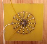
He doesn't need restraining he needs encouraging! But I do see your point! For proof of concept, Simple LEDs could be powered from PICAXE pins, esp the super-bright ones that can work off about a milliamp or so. I seem to have them coming out of my ears, too. The 5 off, LED bulbs I'm currently using form a bar-graph display, are made up and each one draws about 240mA at 12V. Each one is made of 12 'arms' of 3, 1206, SMD, Super-bright LEDs in series with a 1206, SMD, 100R resistor. These are all hand-soldered to a bespoke PCB which I designed, made and assembled. That's over 200 little bl...y bits the size of a pin-head soldered to pads not much bigger! I'm having second thoughts about my choice of output transistor, the BUZ11, as I didn't appreciate the high currents required for quick switching. Perhaps some fairly meaty NPN power transistors would be a better choice? I don't know I've been using BUZ11s for so long their like an old friend!
 

Dicky Mint

Senior Member
Thing is I still want them to flash with the music, so to speak, and I don't know how to both flash them and PWM them at the same time!
 

nick12ab

Senior Member
@eclectic - I think he means he wants to be able to adjust the brightness with PWM in addition to using the flashing to the music.

@Dicky Mint - you could use one output for the flashing and another for PWM. Connect the LED between the two.
 

Dicky Mint

Senior Member
Each LED bulb will flashing in time with the music but to be able to dim the average, maximum LED output, without changing the sound response, is the problem. Sorry I'm probably not being very clear I've been working on this forever and its familiar to me but I forget its not to other people.
 

eclectic

Moderator
@eclectic - I think he means he wants to be able to adjust the brightness with PWM in addition to using the flashing to the music.

@Dicky Mint - you could use one output for the flashing and another for PWM. Connect the LED between the two.
1. I'll not guess, but wait for Rick.

2. The LED units are 12v 240 mA.


It's possible to both flash and Pwm from the same pin.
("bursts" of modulated output)

e
 

nick12ab

Senior Member
I didn't say you had to change the sound response. PWM on one pin, flashing output on the other.

@eclectic - transistors then!
 

eclectic

Moderator
Each LED bulb will flashing in time with the music but to be able to dim the average, maximum LED output, without changing the sound response, is the problem. Sorry I'm probably not being very clear I've been working on this forever and its familiar to me but I forget its not to other people.
Straightforward.
Set the PWM level Say 10kHz frequency.

"Human" flash at say 10Hz

e
 

Dicky Mint

Senior Member
nick that seems to be a similar solution to one I tried before but modulating the BUZ11s ground pins with an additional PWM MOSFET. If I could get it working that would be a solution which could work in an electronic or PICAXE context if the proof of concept was affirmative. This is all a bit confused as I'm working on a few concurrent and sometimes interactive problems at once, bad for Karma but there it is! Would the ULN2803 mind if one strobed its ground pins?
 

eclectic

Moderator
nick that seems to be a similar solution to one I tried before but modulating the BUZ11s ground pins with an additional PWM MOSFET. If I could get it working that would be a solution which could work in an electronic or PICAXE context if the proof of concept was affirmative. This is all a bit confused as I'm working on a few concurrent and sometimes interactive problems at once, bad for Karma but there it is! Would the ULN2803 mind if one strobed its ground pins?
Just to be absolutely clear:

Your input(AFAIK) is presently a potentiometer,
but soon a microphone.

1. What will control the PWM level (or LED brightness)?

2. What will control the flashrate?


e
 

Dicky Mint

Senior Member
Just to be absolutely clear:

Your input(AFAIK) is presently a potentiometer,
but soon a microphone.

1. What will control the PWM level (or LED brightness)?

2. What will control the flashrate?


e
One input is a potentiometer which I want to use with an adc to control, via PWM, the overall LED current and hence the overall brightness

I am using another adc input to input sound via a microphone and amplifier.

I am trying to create a large, bar-graph type display with LED bulbs.

If I could modulate the pins I'm using as outputs for the display drivers that would probably solve many of my problems.

Flash rate is determined by the microphone input
 
Last edited:

eclectic

Moderator
Thanks for post #24.

Now, for experiment time. :)

Do you have a working prototype board / BB
AND a picxe chip
AND an LED + resistor.

If so, you can start some PWMout experiments

e
 

Dicky Mint

Senior Member
hmm sorry, one's in the post (really!). All I've got now is my little old, Heath Robinson Breadboard, and combined programming socket! But "me thinks" I do have a reliable PICAXE-08M2 board with an LED and resistor on C.0. If this would do I we can go ahead. Trouble is I've not got access to a soldering iron at this moment and its not connected to a breadboard. So I suspect we'll have to take a rain check. Are there and other bits I need which I cold use the time to gather?
 

eclectic

Moderator
hmm sorry, one's in the post (really!). All I've got now is my little old, Heath Robinson Breadboard, and combined programming socket! But "me thinks" I do have a reliable PICAXE-08M2 board with an LED and resistor on C.0. If this would do I we can go ahead. Trouble is I've not got access to a soldering iron at this moment and its not connected to a breadboard. So I suspect we'll have to take a rain check. Are there and other bits I need which I cold use the time to gather?
Curses Moriarty, foiled again! (for the moment)

Man 1, p.27 shows pwm on C.2 (Leg 5)

Now, these are VERY rough ideas at the moment.
Inputs: Microphone/Potentiometer/Switch

Outputs:
LED's Pwm controlled AND flash-rate controlled.
Press switch. = Interrupt routine to ReadADC pot.
Release switch = return to main program
Main prog =
Read sound level
Manipulate value
Adjust "toggling" frequency

e
 

eclectic

Moderator
You mean like keep the on/off ratio but control with frequency?

Fiendish Holms! Another brilliant idea!

More (hopefully relevant) questions.

1. Can you post a photo of your LED displays?

2. Will ALL the displays be at the same brightness level, (pwmout)
OR, will they be at different levels?

As a total aside, you've latched onto the Sherlock Holmes,
whereas I was using the old "Goons" Gritpype-Thynne Moriarty.

e
 
Last edited:

Dicky Mint

Senior Member
Yeah I think I've got one somewhere, I'll do it tomorrow. 2. all bulbs, when on, will be the same brightness level. "Neddy fallen down de well" and all that! See ya tomorrow?
 

Dicky Mint

Senior Member
Sams Box Bargraph 01.JPGSams Box Bargraph 02.JPG

Hi I thought I'd post some pictures of my LED bulbs. Also I received my AXE091 board today so I'm in clover! I have a reliable prototyping set up at last. (I hope!)
 

Dicky Mint

Senior Member
Sams Box Bargraph 03.JPGSMD Star PCB.jpg

Here's a couple more pictures I'm just trying out how to add pictures really but they might be interesting to someone!
 

SAborn

Senior Member
36 leds per segment, no wonder the poor bugger almost jumped out of his wheel chair, it would be just short of a welding flash for the unexpected.

It would be neat if you could do each wheel in groups of 4 spokes and have them revolve around the ring.
 
Last edited:

Dicky Mint

Senior Member
Ok point taken!!! I really was just trying to get the most light output for my current dollar! I was looking into a mains version with incandescent bulbs and I was comparing my LED bulbs with them. That's my excuse anyway. But I take your point, if I could dim the whole palaver or knock the corners off the driving square wave it should be a little kinder on the eye!

That would indeed be good but I think I'll leave that for a future project!
 
Last edited:

eclectic

Moderator
snipped

Also I received my AXE091 board today so I'm in clover!
I have a reliable prototyping set up at last. (I hope!)
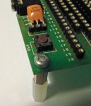
A suggestion for your new toy. :)

I own two AXE091 boards.

I desoldered the resonators on both,
replacing each with a three pin socket.

Now, it's easy to change the resonator
between 4, 8 or 16 MHz.

Obviously, it's not as robust as a
soldered component,
but for quick testing, it works.

e
 

Attachments

Dicky Mint

Senior Member
I like it! Good tips like that are always welcome! I want to mount an on/off switch to my board and I'll stick a battery pack to the back. I should also attach feet to the four corners of the board. Perhaps I'll make tomorrow a hardware fixing day!
 

Goeytex

Senior Member
Dickey Mint,

What you are wanting to do can be accomplished by PWM'ming the PWM. This can be done in code.

Another thing .. "rounding the corners" of the PWM will do very little as far as human perception of rise of brightness due to the nature of the human eye UNLESS the corners are rounded over a time period of more than about 15ms. Then the PWM would be so slow that it would not work on the human eye since PWM dimming depends upon the persistence of the eye. The eye/brain cannot tell the difference between a PWM frequency of 100 hz and 10,000 hz. But get below about 60hz
and we can see the light begin to flicker ....

Another correction: The 14M2 does indeed have 4 PWMs just like the 20M2

Try this code. What it does is "PWM the PWM". Connect 10K pots to each ADC.

Code:
#picaxe 14M2
setfreq M32
pwmout pwmdiv4, c.2, 249, 500

do
  readadc10 B.1,w0  
  readadc10 B.2,w1
  w1 = w1 * 2
  w2 = 2000 - w1
  pwmduty C.2, w0
  pauseus w2 
  pwmduty c.2, 0
  pauseus w1
loop
 
Last edited:

nick12ab

Senior Member
Then the PWM would be so slow that it would not work on the human eye since PWM dimming depends upon the persistence of the eye. The eye/brain cannot tell the difference between a PWM frequency of 100 hz and 10,000 hz. But get below about 60hz
Well, you can if you move the object being PWM'd or where your eyes are pointing at.
 

Goeytex

Senior Member
"Well, you can if you move the object being PWM'd or where your eyes are pointing at. "

How is that relevant to this discussion ?
 
Top