This entry (under construction) describes a Picaxe-controlled led lighting controller for household 12v led lighting.
It originated with a desire to replace MR16 halogen lamps in the kitchen, at a time when redecoration was contemplated. It was created originally in 2004, when the range of led luminaires was much more limited than today. It uses on/off control of two channels, and pwm control of one channel, where multiple brightness settings were desired.
The hardware has evolved and the current incarnation has been running continuously for five years. The leds in use have also evolved as technology improved.
The code was written using a simple finite-state-machine structure that I have previously published here. It has the advantage that the program structure is pre-defined, and leave little to be programmed in a new project apart from the project related content. Specifically what the programmer has to do is a) define the events (and states if required) that are required, b) program the event monitor to detect the events, and c) program the individual actions needed for each event-driven state transition. That it pretty well it! Using a pre-built structured framework means that the code will run immediately, even before all the functions are coded, and as this example shows, the code can be read, understood, and modified many years after origination. It isn't 'efficient' in terms of machine cycles per function. But it is hugely efficient in terms of development and maintenance time.
Over the next few days I will post the code, the schematic for the hardware, and some photographs.
Project summary
This unit will control strings of parallel connected 12v leds, used in the original case both as ceiling mounted MR16 leds and as under-cupboard lights of various types. Typical power levels are up to about 30W per string, provided the supply is sufficient. In the original case, power cuts were a regular occurrence, so the lighting in the kitchen was floated on 200Ah of lead-acid battery, itself floated on the mains. Thus the supply provided both a high-current source and a backup capability.
The design has four channels, though the original use only requires three channels: channel 1) multiple levels of brightness, channel 2) and channel 3) simple on/off control. All normal use adjustments require a short press on the control buttons, which are parallel connected so may be installed e.g. at each doorway, by the sink, etc. In practice, two levels of brightness are considered sufficient though the code could handle any number of levels if needed. There is a special case where the brightest level is presettable. It was found that the newest leds were brighter than expected, and a way was required to limit the level. A long press on channel 1 will vary the channel 1 brightness slowly between dim and maximum and back continuously. Any further press will set the maximum brightness at the level at the time of the press.
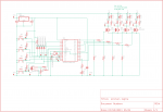
The design is based on a Picaxe 28x2 running at 65MHz. This is to ensure all presses are captured, and to allow certain code features including improved timing over the 18M2 that was used in the first version.
The Picaxe controls the lighting strings directly through one IRF520 Mosfet per channel. Wiring in this ear of the assembly needs to be capable of carrying several amps, according to the use case. The on resistance of the Mosfet is very low and so heatsinks are not required on the on/off channels. In the case of the pwm channel, a single foldback clip (paper clip) clipped on the Mosfet tab has proved sufficient.
Here is the 2014 schematic
and the code is here
It originated with a desire to replace MR16 halogen lamps in the kitchen, at a time when redecoration was contemplated. It was created originally in 2004, when the range of led luminaires was much more limited than today. It uses on/off control of two channels, and pwm control of one channel, where multiple brightness settings were desired.
The hardware has evolved and the current incarnation has been running continuously for five years. The leds in use have also evolved as technology improved.
The code was written using a simple finite-state-machine structure that I have previously published here. It has the advantage that the program structure is pre-defined, and leave little to be programmed in a new project apart from the project related content. Specifically what the programmer has to do is a) define the events (and states if required) that are required, b) program the event monitor to detect the events, and c) program the individual actions needed for each event-driven state transition. That it pretty well it! Using a pre-built structured framework means that the code will run immediately, even before all the functions are coded, and as this example shows, the code can be read, understood, and modified many years after origination. It isn't 'efficient' in terms of machine cycles per function. But it is hugely efficient in terms of development and maintenance time.
Over the next few days I will post the code, the schematic for the hardware, and some photographs.
Project summary
This unit will control strings of parallel connected 12v leds, used in the original case both as ceiling mounted MR16 leds and as under-cupboard lights of various types. Typical power levels are up to about 30W per string, provided the supply is sufficient. In the original case, power cuts were a regular occurrence, so the lighting in the kitchen was floated on 200Ah of lead-acid battery, itself floated on the mains. Thus the supply provided both a high-current source and a backup capability.
The design has four channels, though the original use only requires three channels: channel 1) multiple levels of brightness, channel 2) and channel 3) simple on/off control. All normal use adjustments require a short press on the control buttons, which are parallel connected so may be installed e.g. at each doorway, by the sink, etc. In practice, two levels of brightness are considered sufficient though the code could handle any number of levels if needed. There is a special case where the brightest level is presettable. It was found that the newest leds were brighter than expected, and a way was required to limit the level. A long press on channel 1 will vary the channel 1 brightness slowly between dim and maximum and back continuously. Any further press will set the maximum brightness at the level at the time of the press.
The design is based on a Picaxe 28x2 running at 65MHz. This is to ensure all presses are captured, and to allow certain code features including improved timing over the 18M2 that was used in the first version.
The Picaxe controls the lighting strings directly through one IRF520 Mosfet per channel. Wiring in this ear of the assembly needs to be capable of carrying several amps, according to the use case. The on resistance of the Mosfet is very low and so heatsinks are not required on the on/off channels. In the case of the pwm channel, a single foldback clip (paper clip) clipped on the Mosfet tab has proved sufficient.
Here is the 2014 schematic
and the code is here
Attachments
-
17.1 KB Views: 29
Last edited: