Inspired by the macro rail project posted here a few weeks ago, I decided I wanted to experiment a little with PICAXE processors, too.
My project is a millisecond (or at least close to that) flash delay timer for high-speed photography. For those that aren't familiar with that kind of photography, high-speed photography is the art of taking photographs of high-speed phenomena, typically a popping water-balloon or a bullet breaking an object. The setup is usually a dark room where the camera is set to "bulb," that is, the shutter is open, and the flash is fired at the moment when the balloon is popped or the bullet enters or leaves the object. Firing the flash at the right moment usually involves a sound-activated trigger placed in a position where the delay of the sound propagating from the gunfire matches the bullet's travel distance. When the microphone of the sound-activated trigger picks up noise, the trigger shorts the input of the flash unit and illuminates the subject. Changing the distance between the microphone and the sound of the noise makes it possible to time the flash delay.
But why move the microphone around when you can easily build a unit with a programmable millisecond delay? And while you're at it, why not have the unit accept a variety of other detectors, such as a broken IR or laser beam, light, etc.? Oh, and maybe have it fire an entire series of flashes with a programmable delay inbetween once it has ignored an initial series of preflashes?
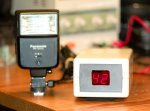
That's a task for the 08M, of course. The detailed documentation may be found here. The near final timer looks like this:

My project is a millisecond (or at least close to that) flash delay timer for high-speed photography. For those that aren't familiar with that kind of photography, high-speed photography is the art of taking photographs of high-speed phenomena, typically a popping water-balloon or a bullet breaking an object. The setup is usually a dark room where the camera is set to "bulb," that is, the shutter is open, and the flash is fired at the moment when the balloon is popped or the bullet enters or leaves the object. Firing the flash at the right moment usually involves a sound-activated trigger placed in a position where the delay of the sound propagating from the gunfire matches the bullet's travel distance. When the microphone of the sound-activated trigger picks up noise, the trigger shorts the input of the flash unit and illuminates the subject. Changing the distance between the microphone and the sound of the noise makes it possible to time the flash delay.
But why move the microphone around when you can easily build a unit with a programmable millisecond delay? And while you're at it, why not have the unit accept a variety of other detectors, such as a broken IR or laser beam, light, etc.? Oh, and maybe have it fire an entire series of flashes with a programmable delay inbetween once it has ignored an initial series of preflashes?
That's a task for the 08M, of course. The detailed documentation may be found here. The near final timer looks like this:
Attachments
-
 45.2 KB Views: 14
Last edited:
")