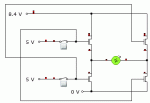
High-Sided N-Channel FET Switching

You can't do it easily, I know. But unless anyone knows of a TO-220 packaged P-Channel that can pass 10A, it's the only solution I have.

The application is essentially to make a giant L293D bi-directional motor controller. The FETs I have available are IRF530s. They have a threshold voltage of 2.4V and are driven by 5V from a PICAXE. They are switching a voltage of between 6 and 8.4V.

So, for the low-sided ones, no problem. But the high sided ones barely turn on at all. I breadboarded it and the motor barely spun while the high-side FET got pretty toasty. Some solutions I thought of are as follows:

  • Massive great 20W resistor on high side of high-side FET to bring voltage down to a low level, but then there'll be practically nothing to drive the motor.
  • Charge pump to double 5V to 10V.
  • Create a second rail by paralleling two*AA batts with main battery, use PICAXE to switch this, which then switches the FET.
  • Don't bother and try and find a beefy enough P-Channel device

Circuit schematic shows the general idea.

Which way is best?
 

Attachments

BeanieBots

Moderator
You'll need a lot more than 10v to use an IRF530 on the high side!

Why not use a P channel?
Can you really not find an H-bridge chip to do 10A? (or module).
Have you searched on here? This has been covered countless times.

I've recently used a VN820-E + relay for bi-directional PWM motor driving @24v.
It's good for 10A.
The VN820-E has quite a large turn on delay and is not designed for PWM but it works well as long as you keep the frequency down.
 
Last edited:
I have recently tried the moderately priced P ch-MOSFET SPP18P06P (60V-18A-13mohm) in a stepdown pos.output s.m.converter, switching up to 5A at 150 kHz with a very small heatsink... but you will need at least 8V supply to turn it on properly.
 
Last edited:

ciseco

Senior Member
Hi,

I've as yet not digisted the data sheet or soldered one up, but I was looking for a beefier L293D type device for a generic shield, I requested a few samples of the drv8432 as it's capable of upto 14A.

Might be unsuitable, just thought it worth a look

Miles
 
Oh, looks easy then. My teacher gave em the impression that there simply weren't such things as P-Channel MOSFETs that could switch that sort of load. Seeing as that's not the case, then I guess the question is simply to make sure I've got the facts right about operating P-Channel devices (not something I've done before).
So, to turn one on I have to pull the gate LOW - well that's just PICAXE 0V, and to turn it off I have to pull the gate HIGH to Vcc,so I'll need to use the PICAXE O/P to drive a small NPN transistor that will generate the required 8.4V.
Correct me if anything there is wrong. And as for base current, how do I calculate what this will be (and thus what resistor will be required to limit it?) For PNP BJTs, I know it is collector current/Hfe, but don't know whether it changes given that a FET is a voltage amplifier.
 
Hi,

I've as yet not digisted the data sheet or soldered one up, but I was looking for a beefier L293D type device for a generic shield, I requested a few samples of the drv8432 as it's capable of upto 14A.

Might be unsuitable, just thought it worth a look

Miles
Looks pretty complicated! Only seems to be available in SMT packages, which I'd rather steer clear of. With four separate PWM channels (i'm only using a 14M :D), it's overkill for what I need, but by all means have a go!
 

Dippy

Moderator
Sorry, I can't follow your schematic.
The problem is a lack of understanding of MOSFETs.
And, yes, all of us were confused at one stage in life so you aren't alone!

There is also the problem that teachers don't understand MOSFETs either.

Let's go through a few fundamentals.
1. Read the Data Sheet DETAILs , a 'threshold' values does N-O-T mean it's fully tuned on
Often it is the gate voltage wrt Source where Ids = a few hundred MICROamps.
2. This Gate voltage is wrt (with resepct to) the Source voltage.
So, if you use a P Chan the gate voltage is NEGATIVE with respect to the source.
Thus you have to read up on the -Vgs vs Rds values.
For non-logic it is often -8 to -12V.
When you start getting on to higher voltages and just switiching the P chan with a simple driver be aware of the max value for -Vgs.

3. If you use an N chan then, again, the Gate voltage MUST be POSITIVE wrt the source.
i.e. the voltage connected to the MOSFET's Source + x Volts.
Your charge pump must be able to go quite high.

If you look at proper drivers for N chan high-sides have a look at how their charge pumps are connected.
 
Top