high power PWM

flak-spammer

New Member
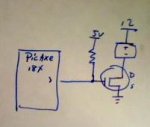
So I'm kinda new to all this stuff but I'm trying to build a PWM controller that could power something pretty hefty I'd like to start out at about 200w. I'm trying to control the input voltage for a peltier and they are pretty high power devices. I'd like to use the picaxe controller to do this but I have no knowledge of what I should do. Anyone have any suggestions? Circuit Diagrams etc would be useful.
 

eclectic

Moderator
Welcome to the Forum.

First, there's plenty of info. on Peltier. Just use the search function.

Second, 200W is feasible, but, could you give more information
on your project please?

e
 

sleazyd

New Member
Hey there. OK, that sounds pretty reasonable. 200W, on a 12V peltier cooler (I'm assuming) turns out to be about a 16 2/3 A switch, which is fairly hefty, but doable. You'll probably want o setup a low-side FET or BJT and set your PWM in the 10KHz range.

Size your FET accordingly. Remember that at higher currents, you'll end up having to put a heat sink on the FET. The power loss on the FET is related to current, so if you can get it to run at a higher voltage you may be better off.
 

Attachments

Andrew Cowan

Senior Member
16A, 10KHz, no driver? Sounds like a good way to heat up/burn out your FETs.

Thninking about the (non inductive) load, a solid state relay (SSR) sounds by far the best option. A 40A solid state relay will cost about $15, and can be driven straight from a PICAXE PWM pin.

A
 

boriz

Senior Member
The higher the frequency, the greater the heating due to FET gate capacitance. Best to use a much lower frequency (Peltier devices react very slowly anyway), and parallel a couple of high current / low threshold MOSFETS such as STP55NF06L, available HERE.

Just one of these would probably work, but if you are using a logic level gate drive, direct from the Picaxe, then you can expect a larger-than-ideal Rds-on. Experiment!

A PWM frequency as low as 1 Hz would prolly be ok, but for a direct Picaxe drive, using the timer prescaler, 250Hz is easily achievable and a good compromise.
 

flak-spammer

New Member
I think TEC's prefer to be run at higher frequencies since excessive thermal cycling tend to cause early death. Do SSR's work with higher frequencies or are they limited to lower frequencies.
 

Andrew Cowan

Senior Member
Depends on the relay - most can.

A DC SSR usually consists of a FET driver and transistor and FET.

AC SSRs work with thyristors.

A
 

BeanieBots

Moderator
Peltiers DO NOT like slow PWM drive. The thermal shocks will destroy it quite quickly. The datasheet should give advice on the minimum frequency.
To drive a FET at those currents with a high frequency, you WILL need a proper driver circuit. A simple circuit such as the one posted by sleazyd will simply melt the FET when driven with PWM at the required rate.

If you do not want to build a proper driver etc, then a solid-sate-relay as suggested by Andrew is probably your best bet but be aware that many are designed for AC use and will never turn off if used with DC. Double check with the relay datasheet that it is suitable for what you want.
 

gengis

New Member
They do make high speed DC SSR's these days. They are still somewhat specialized and relatively expensive. The simple direct drive using an axe output is probably wishful thinking. It takes a fair amount of drive to keep a mosfet happy at high speeds. You need to charge and discharge the gate capacitance rapidly, and high current, low drop, low voltage, mosfets generally have higher gate capacity. Those requirements translate into high(er) drive voltages, and currents to move lots of electrons fast - on and off the gate. BTW lots of the ssr's designed for it, have built in DC/DC step up converters and are far from standard - some use three terminals on the "coil" side - 2 power the internal electronics then one terminal is used to "enable" the output to switch. Doesn't mean you can't do it though - but I'd start with a totem pole style output similar to what is inside the axe and power it from the 12V side of things. I had to build a battery bank discharger for testing u.p.s. system 12V batteries. I had no problem with a single mosfet driven from a 555 timer to modulate the pulse width - the 555 was running from the 12 V and is able to source or sink 200 milliamps (versus the axe's 20 ma) and running from 12 V it worked with no problems. The load resistors drew 20 amps at 12 V. I forget the mosfet I used - some TO3 case thing from RCA (a free sample). Driving brush type motors - the mosfet has to be protected with high speed "damper" diodes and a snubber.
 

D n T

Senior Member
MOSFET driver chip ?

I found a MOSFET driver chip you might want to have a look at I think it will let you drive off a PICAXE without much else

TC4420

have a look if you like
 

flak-spammer

New Member
So is there no way I could do a power amplifier like this http://www.overclock.net/peltiers-tec/395259-quad-tec-water-chiller-project-ultrasonic2.html#post4716264 Or is something like this possible while using a picaxe to supply the PWM. I'm trying to use the picaxe as a temperature feedback so that I can keep Thot (hotside temp) and Tcold (coldside temp) of the peltier within a certain range. So I'll probably have temp feedback that will change the PWM duty cycle based on the current temp. Also I'd like to have manual control over it as well.
 

manie

Senior Member
I could'nt help but notice that Dippy is shining in his absence on this thread, I wonder if all this Mosfet talk has something to do with it ? Just a quick "on the side".

TC4420's worked quite well for me, remember my Mosfet saga ? However, the Mosfets were never quite able to power the load above about 10-15 amp total. And that was with anything between 3 - 6 Mosfets in parallel. Maybe using the 555 at higher voltages could work better as Mosfet driver ?
 

flak-spammer

New Member
Those links look like they should be useful only problem is I'd need something that could supply a lot more power than what is listed there. Also it's using a basic stamp instead of a picaxe.
 

gengis

New Member
From my understanding you only intend to cool too. Take the useful bits and build your own version. You don't need a lot of what he's done there. Likewise, the code would be simpler, and require transposition to picaxe-speak and the pwm.
 
Top