prajesh828
New Member
Here is my program. I want to see if my ir sensors are working or not.
i have attached my files what m using.
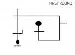
Used 28x2 on picaxe. Now Should i use readadc A.0 or irin? It should clear the maze of line. Line is black line while rest is white. So confused.
A.0 and A.3 are my sensor pins.
Code:
#rem

***********************************************************************
                                                                          *
 *     DESCRIPTION                                                        *
 ************************************************************************ *
 * This program Tests the robot whiskers and moves to the appropriate navigation subrouotine.
 * RIGHT FORWARD IS PIN   , BACKWARD PIN
 * LEFT FORWARD IS PIN    , BACKWARD PIN
 * RIGHT SPEED PWM
 * LEFT  SPEED PWM
#endrem
        symbol swR = C.4     'Define input pin Left whisker
        symbol swL = C.6     'Define input pin Right whisker

#rem
 ***********************************************************************
 *
 *     Define output pin usage
 ***********************************************************************
#endrem
        symbol  PIEZO   =  B.1  	' AUDIO OUTPUT TO PIEZO SPEAKER
        symbol  ledr    =  B.0   	' Left LED
        symbol  ledl 	=  B.2 	' Right LED

#rem

***********************************************************************
 *
 *     Define variables                                                  *
 **********************************************************************
#endrem

      '  symbol	time	= b7
      '  symbol	whiskers	= b8

#rem
 ***********************************************************************
 *
 *     Program Initialisation
 ************************************************************************

 The program starts execution here when the processor is powered up, is
 reset, and after the program has been downloaded.

 The output pins are immediately cleared to stop the motors, and then the
 program issues two low frequency beeps on thepiezo transducer to indicate
it has initialised, and then waits 5S to allow the other processors to be
initialised ( and power to be applied to the motors if switched off ).
#endrem


tune B.1, 6,($40,$40,$45,$44,$45,$40,$02)


main:
	forward a pwmout C.1, 99, 200
	forward b pwmout C.2, 99, 198
	irin A.3,b0
	irin A.0,b1
	debug


	if b0>180 and b1>180 then go
	if b0>180 and b1<180 then left
	if b0<180 and b1>180 then right
	if b0<180 and b1<180 then rukhja

goto main

go:
	high ledl
	forward a
	forward b
	high ledr

goto main

left:
	high ledr
	forward a
	backward b
	low ledl
goto main

right:

	high ledl
	forward b
	backward a
	low ledr
goto main

rukhja:
	low ledl
	halt a
	halt b
	low ledr
goto main
i have attached my files what m using.
Used 28x2 on picaxe. Now Should i use readadc A.0 or irin? It should clear the maze of line. Line is black line while rest is white. So confused.
A.0 and A.3 are my sensor pins.
Attachments
-
27.1 KB Views: 30
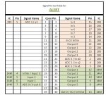
 . Ya it is the alertbot 2.1 i talked about.Sorrry for the confusion.