Help with Servo and Servopos Commands

Tricky Dicky

Senior Member
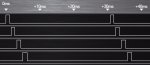
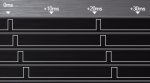
I have written a program to use a modified AXE024 board to drive a servo to open a gate on a model railway layout. The program is using code snippets from the AXE024 data sheet to control the speed of movement and the positioning of the servo. At the end of each movement I am experiencing a slight random twitch or two in the servo, the twitch seems to be something to do with the programming or the PICAXE 08M2 firmware. I have tried all the usual remedies regards power supplies and I am using batteries during this testing stage. If I remove the servo from the circuit and replace it with an LED, I can see the LED flicker at exactly the same point which seems just moments after the servopos command has completed the move. One positive is that after the twitches the servo holds it position without any further twitching.

Looking at the possibility of eliminating these random twitches in software, there is a Servopos (pin) Off command in the manual which is not explained and I was wondering if adding that command immediately after the movement loop in each sub-routine of the attached program would help? The manual states that switching the pin being used by the servo command low, switches off the servo command would this help especially if the servo command was removed from the initialisation routine in the attached program and added to the start of each sub-routine?

Richard
 

Attachments

erco

Senior Member
Try adding these two commands at the very start of your program:

PAUSE 255
DISCONNECT

Should help reduce glitching, but be aware that you will have to to a HARD RESET each time you program the Picaxe. That is, turn Picaxe power on AFTER you click "Program" in the editor. "Disconnect" causes this. The PAUSE is just good practice to let voltages stabilize at powerup.
 

abenn

Senior Member
I've got PICAXE 08M2s programmed to drive servos to change the points, switch the power to the frogs, and switch the LEDs on my mimic panel. I've had exactly the same problem as the OP is experiencing, with the servos often twitching after they've moved to the required position. I send a "servo c.2 OFF" command immediately after moving the servo, but they still twitch.

One solution I've found is to use a good quality digital servo (I've tried a Hitec), but for me it's not worth the extra expense compared with cheap analogue micro servos I've got from Hobby King. I also tried a cheap Hobby King digital servo, and it didn't twitch, but after a few cycles it started buzzing when at rest. That could be eliminated by using another PICAXE channel to switch the servo power supply off when it's finished its movement.
 

Tricky Dicky

Senior Member
I've got PICAXE 08M2s programmed to drive servos to change the points, switch the power to the frogs, and switch the LEDs on my mimic panel. I've had exactly the same problem as the OP is experiencing, with the servos often twitching after they've moved to the required position. I send a "servo c.2 OFF" command immediately after moving the servo, but they still twitch.

One solution I've found is to use a good quality digital servo (I've tried a Hitec), but for me it's not worth the extra expense compared with cheap analogue micro servos I've got from Hobby King. I also tried a cheap Hobby King digital servo, and it didn't twitch, but after a few cycles it started buzzing when at rest. That could be eliminated by using another PICAXE channel to switch the servo power supply off when it's finished its movement.
I have to agree that quality servos are more likely to be less troublesome, however I do not think this the case here as I said in my last post remove the servo and replace it with an LED and I can see the LED flickering at exactly the same point that the twitching occurs without any external influences. This suggests to me that the problem is in software.

Richard
 

abenn

Senior Member
That's interesting, I missed the point about getting a flicker with an LED. I've just tried that with my circuit and, it's difficult to discern, but sometimes I believe there is a slight flicker at the end of the servo movement routine.

I've just tried adding erco's lines at the beginning of my program, and it certainly seems (subjectively) to reduce the incidence of twitching. But it certainly doesn't eliminate it; I got a couple of twitches in about 50 servo movements. The lines do no harm though, so long as I remember about the hard reset routine when reprogramming, so I'm going to leave them in my program.
 

hippy

Technical Support
Staff member
SERVO and SERVOPOS commands are convenient and good enough to use in most cases, but the best way to get rock-solid, glitch-free servo control is to bit-bang the servo signal rather than rely on those commands.

The following should work but is untested on actual hardware. It probably needs some explanation as to how it works but adjust the SPEED constant to change how quickly it moves from open to closed and vice versa -

Code:
#Picaxe 08M2
#No_Data

Symbol SERVO_PIN  = C.2
Symbol DUMMY_PIN  = C.0
Symbol BTN_OPEN   = pinC.3
Symbol BTN_CLOSE  = pinC.4

Symbol fromPos    = w0
Symbol toPos      = w1
Symbol pulseTime  = w2
Symbol pauseTime  = w3

Symbol POS_OPENED = 199
Symbol POS_CLOSED = 100

Symbol SPEED      = 100

#Macro Move( fromNum, toNum, pinName, label )
  fromPos = fromNum * 100
  toPos   = toNum   * 100
  Low SERVO_PIN
  Do
    pulseTime = fromPos / 100
    pauseTime = 2000 - pulseTime
    PulsOut SERVO_PIN, pulseTime
    PulsOut DUMMY_PIN, pauseTime
    Select case fromPos
      Case < toPos : fromPos = fromPos + SPEED Max toPos
      Case > toPos : fromPos = fromPos - SPEED Min toPos
      Else         : If pinName = 1 Then label
    End Select
  Loop 
#EndMacro

Init:  Move( POS_CLOSED, POS_CLOSED, BTN_OPEN,  Open  )

Open:  Move( POS_CLOSED, POS_OPENED, BTN_CLOSE, Close )

Close: Move( POS_OPENED, POS_CLOSED, BTN_OPEN,  Open  )
 

abenn

Senior Member
Thanks for posting that hippy. It's way more advanced than my basic coding, so I have a very basic question before I try it out in a circuit that's already built:

My servo output is from c.1 and my on/off switch to activate the servo goes to c.3 via the standard "Input Device 1 - Switches" resistor circuit in the manual; switch closed drives it one way, switch open drives it the other.

So, I presume I change SERVO_PIN to c.1 instead of c.2, but what are the DUMMY_PIN, BTN_OPEN and BTN_CLOSE symbols for?

I hope this helps Tricky Dicky too. If not, apologies for taking over the thread :)
 

Tricky Dicky

Senior Member
Thanks for posting your code Hippy as soon as possible I will try to download it onto my test circuit, domestic matters having prevented any attempt today. Like abenn some aspects of your code are beyond my understanding at the moment but I dearly would like to learn from this project and would appreciate any explainer you can offer.

abenn
Check out your messages on NRM and no worries over taking over the thread the more contributions the better.

Thanks again, Hippy I will report back once I get the opportunity to download the code?

Richard
 

hippy

Technical Support
Staff member
My servo output is from c.1 and my on/off switch to activate the servo goes to c.3 via the standard "Input Device 1 - Switches" resistor circuit in the manual; switch closed drives it one way, switch open drives it the other.

So, I presume I change SERVO_PIN to c.1 instead of c.2, but what are the DUMMY_PIN, BTN_OPEN and BTN_CLOSE symbols for?
The change to SERVO_PIN is correct, but there is some slight modification of the code needed to handle a single switch rather than two buttons which I interpreted Tricky Dicky had.

Modified code is shown below, again untested on actual hardware. If the switch works the wrong way round change SEL_OPEN to 1 from 0. Increase SPEED to make movement faster or reduce it for slower.

DUMMY_PIN is used to allow a reasonably accurate '20ms minus servo pulse' pause to be generated to create a constant 20ms timing loop. It's a little longer than 20ms with the SELECT CASE code in the loop but should be fairly consistent. We achieve the desired loop timing by generating a long pulse on a pin which is otherwise not used by the hardware; thus whatever that does is not affecting the hardware we have but gives us the time period we need.

BTN_OPEN and BTN_CLOSE are the two pins which I presumed Tricky Dicky had buttons connected to; one button to open the servo, another to close it.

Code:
#Picaxe 08M2
#No_Data

Symbol SERVO_PIN  = C.1
Symbol DUMMY_PIN  = C.0
Symbol SWITCH_PIN = pinC.3

Symbol SEL_OPEN   = 1
Symbol SEL_CLOSE  = SEL_OPEN ^ 1
 
Symbol fromPos    = w0
Symbol toPos      = w1
Symbol pulseTime  = w2
Symbol pauseTime  = w3

Symbol POS_OPENED = 199
Symbol POS_CLOSED = 100

Symbol SPEED      = 100

#Macro Move( fromNum, toNum, switchState, label )
  fromPos = fromNum * 100
  toPos   = toNum   * 100
  Low SERVO_PIN
  Do
    pulseTime = fromPos / 100
    pauseTime = 2000 - pulseTime
    PulsOut SERVO_PIN, pulseTime
    PulsOut DUMMY_PIN, pauseTime
    Select case fromPos
      Case < toPos : fromPos = fromPos + SPEED Max toPos
      Case > toPos : fromPos = fromPos - SPEED Min toPos
      Else         : If SWITCH_PIN = switchState Then label
    End Select
  Loop 
#EndMacro

Init:  If SWITCH_PIN = SEL_OPEN Then
         Move( POS_OPENED, POS_OPENED, SEL_CLOSE, Close )
       Else
         Move( POS_CLOSED, POS_CLOSED, SEL_OPEN,  Open  )
       End If

Open:  Move( POS_CLOSED, POS_OPENED, SEL_CLOSE, Close )

Close: Move( POS_OPENED, POS_CLOSED, SEL_OPEN,  Open  )
 

hippy

Technical Support
Staff member
Like abenn some aspects of your code are beyond my understanding at the moment but I dearly would like to learn from this project and would appreciate any explainer you can offer.
Some of my comments in the above post to abenn might clear a few things up, but let me know which parts need explaining further and I will do my best to clarify.
 

abenn

Senior Member
Thank you so much hippy, for taking the time. I hadn't been able to read Tricky Dicky's code, for clicking on his link simply returned me to this thread, so I didn't realise he wasn't using a single on/off switch :confused:

Anyway, I'll give your revised code a whirl in my circuit shortly, and let you know how it goes.

Edit: Oh dear, I get a syntax error in this line -- #Macro Move( fromNum, toNum, switchState, label )
 

hippy

Technical Support
Staff member
Oh dear, I get a syntax error in this line -- #Macro Move( fromNum, toNum, switchState, label )
You will need to compile using PE6.

If you are using PE6 check the menu File -> Options -> Compilers -> BASIC Pre-Processor -> Use pre-processor option is ticked, then OK.
 

abenn

Senior Member
OK, I'd already checked for updates, and my PICAXE Programmer only pointed me to v5.5, which I was already on. Anyway, I've found 6.0 now (initial search in PICAXE web site for "PE6" took me to v5.5 download again) and your program compiles without error. Thank you. Now I've just got to see what it does, and then try to understand why.
 
The change to SERVO_PIN is correct, but there is some slight modification of the code needed to handle a single switch rather than two buttons which I interpreted Tricky Dicky had.

Modified code is shown below, again untested on actual hardware. If the switch works the wrong way round change SEL_OPEN to 1 from 0. Increase SPEED to make movement faster or reduce it for slower.

DUMMY_PIN is used to allow a reasonably accurate '20ms minus servo pulse' pause to be generated to create a constant 20ms timing loop. It's a little longer than 20ms with the SELECT CASE code in the loop but should be fairly consistent. We achieve the desired loop timing by generating a long pulse on a pin which is otherwise not used by the hardware; thus whatever that does is not affecting the hardware we have but gives us the time period we need.

BTN_OPEN and BTN_CLOSE are the two pins which I presumed Tricky Dicky had buttons connected to; one button to open the servo, another to close it.

Code:
#Picaxe 08M2
#No_Data

Symbol SERVO_PIN  = C.1
Symbol DUMMY_PIN  = C.0
Symbol SWITCH_PIN = pinC.3

Symbol SEL_OPEN   = 1
Symbol SEL_CLOSE  = SEL_OPEN ^ 1
 
Symbol fromPos    = w0
Symbol toPos      = w1
Symbol pulseTime  = w2
Symbol pauseTime  = w3

Symbol POS_OPENED = 199
Symbol POS_CLOSED = 100

Symbol SPEED      = 100

#Macro Move( fromNum, toNum, switchState, label )
  fromPos = fromNum * 100
  toPos   = toNum   * 100
  Low SERVO_PIN
  Do
    pulseTime = fromPos / 100
    pauseTime = 2000 - pulseTime
    PulsOut SERVO_PIN, pulseTime
    PulsOut DUMMY_PIN, pauseTime
    Select case fromPos
      Case < toPos : fromPos = fromPos + SPEED Max toPos
      Case > toPos : fromPos = fromPos - SPEED Min toPos
      Else         : If SWITCH_PIN = switchState Then label
    End Select
  Loop 
#EndMacro

Init:  If SWITCH_PIN = SEL_OPEN Then
         Move( POS_OPENED, POS_OPENED, SEL_CLOSE, Close )
       Else
         Move( POS_CLOSED, POS_CLOSED, SEL_OPEN,  Open  )
       End If

Open:  Move( POS_CLOSED, POS_OPENED, SEL_CLOSE, Close )

Close: Move( POS_OPENED, POS_CLOSED, SEL_OPEN,  Open  )
Hippy, What if it is an ON-ON switch ie SPDT so there will always be a constant high on one of the two input pins?
 

hippy

Technical Support
Staff member
Hippy, What if it is an ON-ON switch ie SPDT so there will always be a constant high on one of the two input pins?
The pragmatic answer is to just treat that SPDT as a SPST switch. Having two inputs just complicates things when each of the two inputs will always be the inverse of the other.

That said; the two input example in post #6 should work with an SPDT switch, or an ON-OFF-ON three way switch.
 

Tricky Dicky

Senior Member
Wow I step out of the house for a few hours and things have moved on. Just to clarify in my original post the two inputs were from a changeover switch (ON ON) built into a point motor but as you say the same can be achieved with SPST on one input simply using the 1 or 0 to trigger different routines ie OPEN or CLOSE. This will release another output for the indicator LEDs since the pin used for DUMMY_PIN was originally an LED output. I kinda understand the need for DUMMY_PIN, but might come back to you on that one. In the meantime I will try to workout how to trigger the routines from a single input. Thanks Hippy, and abenn and Tedoubleudee for the code and contributions. Hippy I hope you do not mind if I come back to this one for further clarification.

Richard
 

hippy

Technical Support
Staff member
I kinda understand the need for DUMMY_PIN, but might come back to you on that one.
It is basically a clever trick; generate the servo pulse on one pin, generate another pulse on the dummy pin, then repeat, and the combined timing for the loop is set as we want it -

Code:
Do
  PulsOut SERVO_PIN,  200 ;  2ms servo pulse - 200 x 10us = 2000us
  PulsOut DUMMY_PIN, 1800 ; 18ms dummy pulse - (2000-200) = 1800 x 10us = 18000us 
Loop                      ; 20ms total loop time
Code:
              __            __            __
SERVO_PIN ___|  |__________|  |__________|  |___

                 __________    __________    ____
DUMMY_PIN     __|          |__|          |__|

             |<>|<-------->|<----------->|
              2ms   18ms         20ms
Put you hand over the bottom DUMMY_PIN output and simply pretend it doesn't exist :)

PULSOUT has traditionally been used in bit-banged servo loops as it allows a better resolution than PAUSE and also works on any PICAXE but does use up an extra pin.

There are tricks to save an actual output pin being used, by fooling the compiler into using an input only pin, ie C.3 on an 08M2; "b27 = C.3 : PulsOut b27, pauseTime" ...

However PAUSEUS can be used these days on M2 and X2 chips so we don't actually need to use a dummy pin at all. I had forgotten that ...

Code:
w0 = 200
w1 = 2000 - w0
Do
  PulsOut SERVO_PIN, w0
  PauseUs            w1
Loop
That gives exactly the same output as two PULSOUT commands do.

So the best approach would be to replace "PulsOut DUMMY_PIN, pauseTime" with "PauseUs pauseTime" in my example code and forget all about the dummy pin !

Hippy I hope you do not mind if I come back to this one for further clarification.
Of course not; fire away.

If you hadn't come back I would probably never have explained the principle and would probably have consequently never remembered the PAUSEUS option.
 
Last edited:

hippy

Technical Support
Staff member
One thought; I know Tricky Dicky said "gate" rather than points, but if controlling points there are probably a few so it might be better to control a number from one PICAXE rather than each having their own.

Running a bit-banged servo loop for multiple servos for that should be reasonably easy for such a project. It's where there is lots of other processing and things going on which can make that more difficult in things like robots.

A 20M2 could control 9 servos from 9 open-close switches, or 5 servos from 5 open-close switches, each with LED status. It is possible to use single bi-colour LED's to have off, green, red, or orange status, or have two separate fully controllable LED's on one pin. If you only needed one LED per servo that would allow 7 to be controlled from a single 20M2.

Of course there are advantages to one 08M2 per set of points and especially if happy to use AXE024 hardware.
 

abenn

Senior Member
I had tried two sets of points per 08M2 but, for some reason, probably the distance between points, I decided it was easiest to have one 08M2 for each point. As well as controlling the points it controls the LED indicators, and switches the power to the "frog". I wasn't aware of the AXE024, and make my own boards.
 

Circuit

Senior Member
Running a bit-banged servo loop for multiple servos for that should be reasonably easy for such a project. It's where there is lots of other processing and things going on which can make that more difficult in things like robots.

A 20M2 could control 9 servos from 9 open-close switches, or 5 servos from 5 open-close switches, each with LED status. It is possible to use single bi-colour LED's to have off, green, red, or orange status, or have two separate fully controllable LED's on one pin. If you only needed one LED per servo that would allow 7 to be controlled from a single 20M2.
I have been following this thread with great interest; Hippy your code and explanations are excellent as ever. I am, however, finding your "reasonably easy" comment not as easy as it is for you. Could you give some indications please of how you sort out the timing for multiple servos with this technique? I cannot seem to fathom how you keep the pulse trains correct in relation to each other. I find the concept of controlling 9 servos from a 20M2 VERY appealing...
 

hippy

Technical Support
Staff member
In theory 9 channel bit-banged servo control should be as easy as -

Code:
#Picaxe 18M2
b0 = 100 : b1 = 110 : b2 = 120 : b3 = 130
b4 = 140 : b5 = 150 : b6 = 160 : b7 = 170
b8 = 180
Do
  PulsOut B.0, b0
  PulsOut B.1, b1
  PulsOut B.2, b2
  PulsOut B.3, b3
  PulsOut B.4, b4
  PulsOut B.5, b5
  PulsOut B.6, b6
  PulsOut B.7, b7
  PulsOut C.0, b8
  w10 = b0 + b1 + b2 + b3 + b4 + b5 + b6 + b7 + b8
  w10 = 2000 Min w10 - w10
  PauseUs w10
Loop
In practice, as seen by the first trace, at 4MHz the loop timing is way longer than 20ms, though perhaps not that problematic.

Running at 32MHz, multiplying servo positions by 8 to compensate and using word variables, and slightly tweaking the pause timing, it can be brought down to 20ms, second trace -

Code:
#Picaxe 18M2
SetFreq M32
w0 = 100*8 : w1 = 110*8 : w2 = 120*8 : w3 = 130*8
w4 = 140*8 : w5 = 150*8 : w6 = 160*8 : w7 = 170*8
w8 = 180*8
Do
  PulsOut B.0, w0
  PulsOut B.1, w1
  PulsOut B.2, w2
  PulsOut B.3, w3
  PulsOut B.4, w4
  PulsOut B.5, w5
  PulsOut B.6, w6
  PulsOut B.7, w7
  PulsOut C.0, w8
  w10 = w0 + w1 + w2 + w3 + w4 + w5 + w6 + w7 + w8
  w10 = 1900*8 Min w10 - w10
  PauseUs w10
Loop
The number of channels can be extended up to the chip output pin limit, though the loop time will increase when the sum of the pulses gets close to and beyond the desired loop time.

For a points switch or similar system where they are either open, closed or moving, all open and closed can be turned on together using "pinsB=? : PauseUs ON_TIME : pinsB=0", and similar for OFF_TIME, which allows a number of others to be moved while still keeping to a 20ms loop time.

Coding gets tricky but it's less complicated if only one servo is allowed to move at a time. Incomplete code ...

Code:
Do
   pinsB = ? : PauseUs ON_TIME
   pinsB = ? : PauseUs OFF_TIME
   pinsB = 0
   Pulsout servoPin, servoTime
   w10 = ON_TIME + OFF_TIME + servoTime
   w10 = 2000 Min w10 - w10
   PauseUs w10
Loop
 

Attachments

Circuit

Senior Member
Hippy, many thanks. Very clear indeed. I now have a weekend of servo-driven playtime ahead!
- Oh, and I do hope that you managed to get lunch in as well...
 

abenn

Senior Member
I've just got round to trying your program hippy, without the recent changes to replace DUMMY_PIN, and it's working fine. Thank you.

Now all I've got to do is figure out how it's working!
 
Last edited:

Tricky Dicky

Senior Member
Hippy

(I have been trying modify your code in post 9 using a single SPST switch as an input and adding in the 5 lines of code from post 18 using the PauseUs command. I am guessing that line 5 of the post 9 code is deleted and the 5 lines of code from post 18 replace lines 25 to 29?)

Hippy, Ignore above post, I have worked it out I did not read all of post 18. Sorry!

Richard
 
Last edited:

Tricky Dicky

Senior Member
Hippy

As you have probably gathered from post #25 I have combined your code in post#9 with the PauseUs command in post #18 and I am pleased to say the servo is moving brilliantly and is absolutely rock solid at the end of each swing, not a twitch, so many thanks for your help there.

What I have been trying to do is to use a couple of the freed pins to light up a couple of LED indicators to indicate when the servo reaches either of the two limits of the swing. I may add that abenn, who contributed to the thread is in very much the same position.

Just to put you completely in the picture the servo is being used on a model railway layout to operate a gated siding linked to the point for that siding. The idea is that when the point is diverted to the siding the gate opens and closes when it is set straight ahead. As the control panel is set some distance away some indication on the panel is required. The point motor has a built in changeover switch which amongst other things can be used to operate indicator LEDs and that may still be on the cards. It is that switch which is being used as the input to the servo circuit. However, I would like the servo circuit to operate the LEDs as this would not only indicate the point had moved but also act as a fail safe to indicate the gate had fully opened/closed as well.

I require the two indicator LEDs to show when the servo reaches the two limits of the swing, with neither lit during any movement of the servo. I have noted that two variables indicate when the servo reaches either end of the swing, b4 fluctuates between 100 and 199, whilst w0 fluctuates between 10000 and 19900. To my thinking either of these could be used to trigger the indicators perhaps with a couple of If.....Then... statements. The problem is where in the code do these statements go, inside the macro does not work whilst the main program consists of two single line subroutines that alternate depending on the input.

Am I thinking along the right lines or does it need a completely different approach?

Richard
 

abenn

Senior Member
I too have come to a dead-end with understanding how the program is working. In my instance, similar to Tricky Dicky's, I want to issue a "high c.1" and "high c.4" command immediately before the servo starts to move, and then a "low c.1" or a "low c.4" (depending on the direction of the move) command after the move is finished. With my limited coding ability it seemed that I could introduce these commands into the init: routine in your code as follows:-
Code:
Init:  If SWITCH_PIN = SEL_OPEN Then

		high c.1
		high c.4
         
	   Move( POS_OPENED, POS_OPENED, SEL_CLOSE, Close )
	   	
		low c.4
       
	 Else
         Move( POS_CLOSED, POS_CLOSED, SEL_OPEN,  Open  )
       End If
I've also tried inserting the lines into the open: and close: routines instead but, wherever I put it, it doesn't do anything. Can you explain a bit more how your program works please?

By the way, I've checked the functioning of the circuit I've loaded your program into by previously running it with my more-simple program that achieves what I want (apart from the twitches!).
 

hippy

Technical Support
Staff member
I require the two indicator LEDs to show when the servo reaches the two limits of the swing, with neither lit during any movement of the servo. I have noted that two variables indicate when the servo reaches either end of the swing, b4 fluctuates between 100 and 199, whilst w0 fluctuates between 10000 and 19900.
That's the way I would do it too. As you say the issue is where to put them. I would put them in the macro, change -

Code:
    Select case fromPos
      Case < toPos : fromPos = fromPos + SPEED Max toPos
      Case > toPos : fromPos = fromPos - SPEED Min toPos
      Else         : If SWITCH_PIN = switchState Then label
    End Select
To -

Code:
Symbol LED_OPENED = C.0
Symbol LED_CLOSED = C.2
Code:
  Select case fromPos

      Case < toPos : fromPos = fromPos + SPEED Max toPos
                     Low LED_OPENED
                     Low LED_CLOSED

      Case > toPos : fromPos = fromPos - SPEED Min toPos
                     Low LED_OPENED
                     Low LED_CLOSED

      Else         : If pulseTime = POS_OPENED Then
                       High LED_OPENED
                     Else
                       High LED_CLOSED
                     End If
                     If SWITCH_PIN = switchState Then label

    End Select
The SELECT CASE handles whether the servo is in motion ( turn both LED's off ) and the ELSE clause only gets executed when the servo is not moving.

The 'pulseTime' at that time will conveniently be 100 (POS_CLOSED) or 199 (POS_OPENED) so will determine which limit has been reached and the appropriate LED can be set.

You might have to change pin allocations for the two LED definitions, and may have to swap Low/High for the LED's.
 

hippy

Technical Support
Staff member
In my instance, similar to Tricky Dicky's, I want to issue a "high c.1" and "high c.4" command immediately before the servo starts to move, and then a "low c.1" or a "low c.4" (depending on the direction of the move) command after the move is finished.
As above for Tricky Dicky I would modify the SELECT CASE so you can light the appropriate LED while the servo is moving, turn it off once the limit has been reached. Both LED's are actually turned off when a limit is reached because that doesn't know which LED had been turned on ...

Code:
Symbol LED_OPENING = C.4
Symbol LED_CLOSING = C.1
Code:
  Select case fromPos

      Case < toPos : fromPos = fromPos + SPEED Max toPos
                     High LED_OPENING
                     Low  LED_CLOSING

      Case > toPos : fromPos = fromPos - SPEED Min toPos
                     Low  LED_OPENING
                     High LED_CLOSING

      Else         : Low  LED_OPENING
                     Low  LED_CLOSING
                     If SWITCH_PIN = switchState Then label

    End Select
You might need to swap the LED pins around and also experiment with which should be High/Low.
 

abenn

Senior Member
Thank you hippy. Actually, I need the LEDs off while the servo is moving from one position to the other, but my circuit uses transistors to drive the LEDs and solid-state relays, so my "High" command results in the LEDs and relays being "off". Anyway, with your suggested code revision above, I'm sure I'll be able to sort out when they're on or off, and which one is on. Thank you again.
 

Tricky Dicky

Senior Member
Success

Hippy,

You are a diamond, everything is working as it should straight out of the box. The other side to this is I feel I am beginning to understand much of the code, not everything but getting there. For now I need to get this project wrapped up but in the future I have another servo project in the pipeline and although I will study your code more and try to understand it all, I hope you do not mind sometime in the future if I resurrect this thread for any clarification that I may require.

Once again thank you Hippy for all your efforts and patience with this project and thanks to all who contributed to this thread.

Thank you Richard
 

abenn

Senior Member
Got there in the end!

Thank you hippy. Your code didn't do exactly what I wanted with respect to the LEDs -- the LEDs switched from one to the other as soon as the switch was thrown, while the servo was still moving to the new position. But, having got the pointer from you about where exactly I should place the commands to switch the LEDs, I've eventually ended up with the following, perhaps not-so-elegant, solution (note that "High" = LED off in this case because of the transistor between it and the 08M2):
Code:
Select case fromPos
      Case < toPos : 	High LED_OPENING
                     	High LED_CLOSING
				fromPos = fromPos + SPEED Max toPos
		
      Case > toPos : 	High LED_OPENING
            		High LED_CLOSING
				fromPos = fromPos - SPEED Min toPos
				
      Else         : If SWITCH_PIN = switchState Then label
			If SWITCH_PIN = 1 then
				low LED_CLOSING
			else
				low LED_OPENING
			endif
    End Select
This gives me both LEDs off while the servo is moving, which is important in my application because the pins that drive the LEDs also control a couple of solid-state relays, which could cause a short-circuit in the tracks if switched too soon while the points are moving.

Hopefully with the passage of time I'll be able to understand more fully what the syntax of the code is. What I've read in the manual still doesn't make #Macro clear to me.
 

Peterrey

New Member
Gents, sorry to butt in on this thread, but I have been experiencing similar issues with 08M2 and 20X2 derived servo drivers (operating signals on a model railway) with spurious 'kicking' of the servo. I will certainly give the 'macro' idea a go to get stability. However, my servo drivers are not operated by switches, but I send ASCII characters from another PICAXE board, and depending on what the character is, a particular servo is operated. I'll try it first, but I may be back at some stage for some advice/help...
 

hippy

Technical Support
Staff member
Code:
      Else         : If SWITCH_PIN = switchState Then label
			If SWITCH_PIN = 1 then
				low LED_CLOSING
			else
				low LED_OPENING
			endif
    End Select
I suspect you may have made a cut and paste error, copied earlier code, because, if your code is like that, it should never get past the first "If ... Then label" to ever reach either LOW command.
 

abenn

Senior Member
I suspect you may have made a cut and paste error, copied earlier code, because, if your code is like that, it should never get past the first "If ... Then label" to ever reach either LOW command.
I've checked again, and that's exactly how it is, and it's working! I've just re-downloaded it to my circuit in case something got altered between original download to the circuit, and cutting-and-pasting for my post, and it still works.

Would this be the correct way to make it work?
Code:
    Else         : If SWITCH_PIN = switchState Then label
			If SWITCH_PIN = 1 then
				low LED_CLOSING
			else
				low LED_OPENING
			endif
                       endif
    End Select
 

hippy

Technical Support
Staff member
I've checked again, and that's exactly how it is, and it's working!
My apologies; you are right. It only jumps to the label when the switch is moved to the next state position, falls through into the IF-ELSE code if not jumping to that label.
 

abenn

Senior Member
No apologies needed, for I've still got a long way to go with learning how to program. Thank you.
 

abenn

Senior Member
Just another thought: If servo and servopos are known to result in servo twitches, and those twitches can be eliminated, as you have demonstrated, by alternate coding, can servo and servopos not be corrected by the program authors so that they don't result in twitches?
 
Hi Hippy, I've been tearing my hair out trying to get this code to work for me but just can't see how I can. I'm fairly new to Picaxe programming but if I understand your code correctly it appears that when no switch movements have been made basically the servo is told to move to where it currently is, ie no actual movement but no twitching either. When the switch is thrown it moves to the other end then continues to "move to stand still" again in it's new position till the next switch change. Right? OK so why can't I get it to work for me?

The answer is I don't have ANY switches in my circuit as I want the program to run autonomously. I want it to move from A to B, wait x seconds, move from B to A, wait x seconds and repeat ad infinitum. Also I'm going to play a sound whilst it is moving but I can do that easily enough. So I program a simple loop to do the above no problem, but the servos twitches like mad just as it did for Tricky Dicky and abenn. So I'm now trying to incorporate your clever macro, but your macro relies on an change of state of an input pin (which I don't have of course) to exit out of. So somehow I need to provide a coded interrupt, but how do I make that happen without, say, a second 08M2 running the wait loop or perhaps a 555 timer in the circuit. Trouble is I've built the circuit and the servo is installed so no chance of adding a couple of micro switches unless I smash it up and start again. But if I do that I can replace the servo with a motor and make it easy peasy. Besides I like your code and may use it in a similar situation to Tricky Dicky, though I confess not to understand all of it!! I mean, why multiply by 100 on one line then divide it again on the next - must be a reason that escapes me :confused: :D! Anyway, not much hair left now so please come to my rescue. Many thanks.
 
Top