cravenhaven
Senior Member
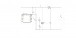
I am attempting to use the pwm output of a 20M2 to construct a simple voltage booster but have been unsuccessful in getting it working properly and was hoping that some of you might be able to point me towards the solution.
Basically my problem is that I cant get it to boost to my desired requirement of 5V @ 1 amp from an input of between 3 and 4.2V. The best I can get into a 4 ohm power resistor is about .9A, which is getting close but the efficiency is woeful at around 30-50%.
The inductor I started using is a PCB mount with a value of 47uH, capable of 3A and a resistance of .097 ohms (MULTICOMP MCBFS7330-470MU), but I also tried a 2.2uH PCB type and standard toroid style with values in the low mH range without any outstanding change in results.
My program simply uses pwmout to set a period of around 100uS and it then monitors the variable resistor to set the duty cycle. I tried other frequencies up to 100KHz but the lower frequency seems to work better. I also tried simulating the cct on LTspice and according to its result I should be achieving what I want") .
.
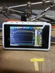
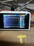
I have the cct built on a breadboard ATM and have monitored the waveforms on a little DSO quad oscilloscope.
The best result I get is with the 47uH inductor and a duty cycle of 30%, gives me an output of about 0.8A and efficiency of 50%. I have attached a representation of the scope output with these settings.
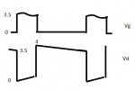
I should add that I tried have the 20m2 directly connected to the FET but it makes no difference and as far as I can tell, the scope traces seem to indicate that it is driving the FET well enough.
Basically my problem is that I cant get it to boost to my desired requirement of 5V @ 1 amp from an input of between 3 and 4.2V. The best I can get into a 4 ohm power resistor is about .9A, which is getting close but the efficiency is woeful at around 30-50%.
The inductor I started using is a PCB mount with a value of 47uH, capable of 3A and a resistance of .097 ohms (MULTICOMP MCBFS7330-470MU), but I also tried a 2.2uH PCB type and standard toroid style with values in the low mH range without any outstanding change in results.
My program simply uses pwmout to set a period of around 100uS and it then monitors the variable resistor to set the duty cycle. I tried other frequencies up to 100KHz but the lower frequency seems to work better. I also tried simulating the cct on LTspice and according to its result I should be achieving what I want
.I have the cct built on a breadboard ATM and have monitored the waveforms on a little DSO quad oscilloscope.
The best result I get is with the 47uH inductor and a duty cycle of 30%, gives me an output of about 0.8A and efficiency of 50%. I have attached a representation of the scope output with these settings.
I should add that I tried have the 20m2 directly connected to the FET but it makes no difference and as far as I can tell, the scope traces seem to indicate that it is driving the FET well enough.
Attachments
-
 81.4 KB Views: 39
 -
 14.8 KB Views: 26