Help with a gosub problem

Hi!
Picked up on an interesting thread in user projects the other day “Connecting a Picaxe 28 X2 to a DCC decoder” and thought this could be interesting if I could make it work. Probably a bit above my ability level at the moment, but what the hec.
I’ve used a 28x1 in place of an x2 and a 7 segment LED display to display the speed steps in place of the LCD used by the person who posted the thread “Sierrasmith71”.
Sorted out the PWM pulse width for the speed steps in the decoder I’m using and using “pulsin” and “select case”, got the speed steps to read out on the 7 segment LED, as per the thread. I then tried to link a motor step procedure to a speed step and this is where I came unstuck!
When I run the program it bypasses the speed step indication and runs the motor through its step procedure and then keeps repeating the program. I put a pause in between the two “gosubs” to see if the speed step indication is working, it is, but after the pause the LED returns to zero and the motor runs. Where am I going wrong?
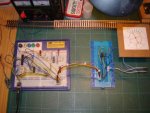
On the attached photo ignore the components to the right of the main breadboard that’s another project I’m working on.
 

Attachments

MPep

Senior Member
After the ROTATE sub-routine, surely you want to RETURN after that? Currently you go straight into STEP1.
 

g6ejd

Senior Member
Yes, your going through the step1: routine once last time so add a RETURN to the end of rotate:
 

eclectic

Moderator
The code snippet under discussion
rotate:
for w5 = 0 to 2400
let b1 = b1 + 1
gosub step1
next w5

step1:
let b1 = b1 & %00000011
lookup b1,(%10100000,%10010000,%01010000,%01100000),b2
let pins = b2
return

goto main
 

srnet

Senior Member
Its could be that the intention is that rotate: falls through to step1:.

Difficult to tell without comments in the code (hint!).
 

g6ejd

Senior Member
I agree some comments in the code as to it's intended operation would help.

Yes, but the pins are being left in the wrong state because of the last run through 'step1:' so clearly a programming logic problem and adding in the return at the end of 'rotate:' is the solution.
 
Hi!
Thanks to you all for replying.
Yes...I agree a RETURN after the Rotate sub routine should make it work - but it don't! I went through that secenario before the post. I also tried END in various places to try and stop falling back inti the GOSUB but no luck. Putting a RETURN at the end of the Rotate sub routine makes no diference.
 

srnet

Senior Member
Yes...I agree a RETURN after the Rotate sub routine should make it work - but it don't!
Wheter it makes it 'work' now or it does not, is not the point really, there could be more than one problem.

If the program is intended to work with a return in that place, then put it in.

If you dont you may well fix one of the problems and miss that its solution because of the missing return.

Very difficult to debug code with bugs left in.
 

g6ejd

Senior Member
I wonder if the case statements are working on return from the sub-routines, perhaps change them to simple If statements...

Does the case statement work OK with word-variables?

Why not put a few diagnaotic print statements in the code, say after the rotate gosub to see if it get back there in the case statement section, then just after the case statements to see if it gets there too, does it follow the current programme locgic/flow?

Observations:

w0 = b0, b1
w1 = b2, b3
w2 = b4, b5
w3 = b6, b7


But b1 is being modified by the track and rotate and step routines. So when you return to the Case statements the value of the Case selection has been changed giving an unstable state.

I suggest you seperate your variables so they are all unique to their intended use. Simply copy pulse to a new word-variable say using bytes 6,7 as / from w3 definition.
 
Last edited:
I think I understand what you are suggesting and have tried implementing it - but still no change! One thing I have noticed is when the Rotate gosub is active the programme is not reading the pulse width on pin0 hence the LED reads 0. Can the Picaxe run to seperate parts of the same programme at the same time? Which the two gosubs are trying to achieve.
 

Technical

Technical Support
Staff member
Dont forget a 28X1 runs at 4Mhz while a 28X2 at 8MHz, so the pulsin value will be out by a factor of 2 at present.
Add a setfreq m8 at the top of the code.
 

g6ejd

Senior Member
I suggest you post your new code that no-longer modifies b1 to see if we can see if there are any other flaws. If you have redefined the variables so that b1 is no-longer being modified inside a subroutine having been used to determine programme flow then I suggest you remove the CASE statements and replace with IF statments. All this pre-supposes the PICAXE functions are working to design too.
 

lbenson

Senior Member
To speculate that PICAXE CASE statements are not working properly is really jumping the gun when neither the problematic code nor its intent are known. It is possible, of course, but as always, user error is the likeliest cause. That possiblility should be eliminated before compiler malfunctions are suggested.
 
The idea behind the project is to detect the PWM pulse width for a given speed step from a model railway DCC controller. Having done that, the 1 to 28 speed steps in the controller (I’m only interested in about 9 of them), instead of controlling the speed of a locomotive, is used to trigger a function in the Picaxe programme. The decoder in effect becomes a stationary decoder and could be used, in conjunction with a Picaxe, to drive almost any ancillary on the layout, very cheaply, from the DCC hand set. I take no credit for this, our friend in Maryland US came up with this flash of inspiration.
What I have done is determine the pulse width produced by my decoder for a particular speed step, not as an absolute, but as the PULSIN command reads them at the input pin irrespective of the internal frequency of the chip. I’m using the change in pulse length as a comparison, not as an absolute.
Using SELECT CASE and value to value detects the speed step selected and executes the programme from that point. The GOSUB I’m using to operate the LED I’ve used many times before with no problem, I doubt I could make it any simpler, and this combination works fine; the LED relates to the speed step.
The stepper motor drive code works fine on its own, again I’ve used it many times in the past.
Its only when I combine the two GOSUBS I hit the problem. (At the moment using only one of the speed steps to debug the programme.)
I guess you realise by now I’m very much at the base of the learning curve when it comes to Picaxe programming and electronics in general and find it difficult to debug a faulty code. I’ve posted the code with the changes I think you suggest, forgive me if I haven’t interpreted them correctly.
 

Attachments

srnet

Senior Member
You use W0 in a select case statement, but then use b1 in two of the subroutines.

Was that intended ?

As mentioned elsewhere w0 uses the same RAM space as b0 and b1, manual2 page 10.
 

hippy

Ex-Staff (retired)
The reuse of b1 within the subroutine doesn't seem to be a problem as it occurs after w0 is used to select the CASE required. Likewise, that b1 is not initialised before entering 'rotate' ( it will be zero if w0 is less than 256 ), and the fall through to 'step1' after the FOR-NEXT stepping shouldn't cause any programmatic problems even if it doesn't move the motor the right number of steps.

But I think we need to go back to the first post and see the problem identified ...

When I run the program it bypasses the speed step indication and runs the motor through its step procedure and then keeps repeating the program. I put a pause in between the two “gosubs” to see if the speed step indication is working, it is, but after the pause the LED returns to zero and the motor runs. Where am I going wrong?
The LED returns to zero; well it would, because the LED is controlled by "pins=" which are being overwritten in the 'step1' code. Easy enough to fix in the 'step' code with -

let pins = b2 | b3

I think people have been looking beyond what the actual problem reported was. If I've misunderstood then perhaps we need clarification on what the observed problem is. Analysis may have been aided by noting the LED shows a number after the motor has turned - assuming it does.
 
For clarity let me reiterate the problem:
Select speed step 1 on the DCC controller. CASE SELECT detects the pulse width for that speed step and initiates GOSUB track1 and the LED shows number 1 as I would expect. 5 second delay (pause 5000) before GOSUB rotate is initiated. LED changes from 1 to 0 and the motor runs through its step count, stops and the LED returns to 1 and the cycle begins again. And will continue to do so until the speed step on the DCC controller is set to 0 with a 0 pulse width which the CASE SELECT detects and the LED shows 0. The 0 on the LED when the motor is running is not the same meaning as the 0 on the LED when no pulse width is present.
What I expected to happen is:
Select speed step 1 on the DCC controller. CASE SELECT detects the pulse width for that speed step and initiates GOSUB track1 and the LED shows number 1, GOSUB rotate is initiated motor steps through its routine and stops. No further action until another speed step is selected on the DCC controller.

Hippy: thank you for your input. I’m not sure I’ve done what you suggest. Please put me right if I’ve misunderstood.
 

Attachments

hippy

Ex-Staff (retired)
Hippy: thank you for your input. I’m not sure I’ve done what you suggest. Please put me right if I’ve misunderstood.
You've done a number of changes so now you would have to change "let pins=b3" to "let pins=b3|b1".

Though whether that fits what you want I'm not sure. I think there are now two problems you have, the LED issue, and the motor repeatedly rotating after turning once.
 
Hippy thanks again.
Yes I now understand what you meant the first time!
Changing the “Let Pins=” to “Let Pins = b3|b1” has cured the problem with the LED, it now works as expected and retains the track number, however the motor step sequence still keeps falling back to GOBSUB rotate and continues to cycle until the speed step is changed.
 

hippy

Ex-Staff (retired)
If you run the program through the Simulator you will see why the rotation continues when the speed does not change; the value read is 24 to 34 so it is repeatedly directed through the 'gosub track1' and the 'gosub rotate' routines, and will continue to do that while the signal remains between 24 and 34.

I would guess you need some means of flagging if the rotation has already been done, for example when the LED is showing 1 or, looking at that in an inverse way, only doing the rotation when it hasn't been previously done, for example when the LED is not showing 1.

So something like the following may work ...

Code:
case 24 to 34
  if b1 <> 1 then					
    gosub track1
    pause 5000
    gosub rotate
  end if
 
No it makes no difference. B1 will be set to 1, through GOSUB track1, before the GOSUB rotate is called. So how can I influence GOSUB rotate by what is held in b1? That is without changing b1.
 

hippy

Ex-Staff (retired)
The first time the code is executed b1 will not be 1, 'gosub track1' will be called ( setting b1 to 1 ), rotate gets called. Next time round the loop, the b1 will already be 1 so it won't run again, until some other track code has run which sets b1 to otehr than 1 ...

But I suspect we are now back to earlier issues that 'w0' and 'b1' usage conflict, which I had forgotten about / missed in the midst of other changes.
 

Paix

Senior Member
No it makes no difference. B1 will be set to 1, through GOSUB track1, before the GOSUB rotate is called. So how can I influence GOSUB rotate by what is held in b1? That is without changing b1.
By kludging it. Make a copy of B1 at the appropriate time into another, fresh, variable and manipulate it to get the result you want, destroying the content when you are finished with it. That way you can have your B1 and eat it too. :)

No marks for elegance perhaps, but why seek an A class answer for a B class question? Indeed it may give you an insight into what is actually going wrong at the moment.
 
Paix. Thanks for your input &#8211; I would try that if I knew how to do it!
I&#8217;ve been working on suggestions that Hippy made but could not find a solution until he reminded me of the W0 b1 conflict. So W12 replaced W0 and this combined with the following bit of code solved the problem. I&#8217;ll try tidying it up later on.
Thanks to all who contributed I&#8217;ve learnt more from this post than I have all year.

case 24 to 34
if b1=1 then
goto main
end if

if b1=0 then
gosub track1

gosub rotate
end if
 

Paix

Senior Member
Very good, always good to keep track of variable usage and more so as programs become larger or more complex. I believe WestAust55, and others, have published tables mapping out the bits, bytes and words for the various Picaxe chips. Printing a cheat sheet and marking off variables as they are used can help illustrate what you have left to play with while keeping track of bit, byte or word overlap issues.

of interest of course is the fact that I believe that the first few bit, byte variables are faster than the rest;first four bytes (two words) and so best used for tight routines with frequent use. I have been known to be wrong of course :)
 
Last edited:

hippy

Ex-Staff (retired)
of interest of course is the fact that I believe that the first few bit, byte variables are faster than the rest;first four bytes (two words) and so best used for tight routines with frequent use.
Lower value numbers are faster to use than higher value but all variables should be equal; their token encoding size is constant whereas for numeric constants it varies.

Most of my optimisation tricks were targeted at smallest code rather than fastest speed and that's become less important with larger program memories, though smaller often means faster. It's usually far more productive and worthwhile concentrating on getting good algorithms and understandable and readable code than worrying over optimisation. There are a few cases where it can be important but not for most programs.
 

Paix

Senior Member
False memory syndrome . . . eek!

Moral of the story, always check the documentation before typing code or comments on threads.
B1.jpg

Never be afraid to admit that you got it wrong.
 
Last edited:
Interesting threads, I guess I&#8217;ll be returning to those in the future!
Now that I&#8217;ve got my base programme working can I bounce something else off you? I want to write some code to accurately position the rotor. Do you think the following idea is realistic and if so, how best do I go about it.

Consider 8 radial positions each 15deg apart (100 steps). At the set up of the project we set a variable &#8220;0&#8221; as the &#8220;start position&#8221;. We know how many steps the motor must make for a given track position from that start position. Say we select track 6 as the first command we know we must step the motor 600 steps; can we then put that number into a variable &#8220;current position&#8221; and remember it? Then for the next selection, say track 8, recall the number in &#8220;current position&#8221; we know the number of steps from &#8220;start position&#8221; to track 8, calculate the difference and step that amount to track 8 which then becomes the &#8220;current position&#8221;. The same would apply if we were moving in the opposite direction except we would subtract steps instead of adding. Then on power down commit to memory the number in &#8220;current position&#8221; so that on power up for the next session we know the position of the rotor.
Well what do you think?
 

inglewoodpete

Senior Member
Sure, I would do the positioning based on the last (known) position of the rotor. However, all systems must be fail safe. You need to determine the position at bootup: even when the power failed during a positioning routine.

Such a case will need a position encoder or a 'home' switch. The bootup routine must be able read the position of the rotor or return the rotor to a known position.
 
Top