Help W Simple Voltmeter

Axel87

Senior Member
Newbie- Trying to learn Picaxe. Need any help I can get.
(Please dont post any links for purchase some premade unit, this is purely educational.)
I'm working on making a bench supply, but have been unable to find any information to help.

So far what I have is-
12V Supply-5A-Laptop Supply
24V Supply-3A-Laptop Supply
A ATX Powersupply- Plan on this being my variable supply
: Off the ATX supply- 5v supply

Currently have 2 08m2 Picaxe chips.
What I am aiming to do seems simple enough, but need some help getting started. :)
The way I see the panel layout would be two 2 way switches- Switch 1. 5V, Variable Switch 2. 12V,24V
W a Potentiometer to set the Variable. I understand this supply is redundant, but just using up scrap supplies while learning Picaxe.
I have a RGB LED that I plan on using for an indicator for supply B=5V G=12 R=24
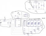
Ultimately- I plan on having 2 7 Segment displays for this. But Ill start easy ;)

From what I have gathered thus far, I need to utilize the Readadc command. Correct? Or do i calibrate the Picaxe to read different resistance values?
If I go with the Readadc, then I can set known values 5V=24V 3.5V=12V 1V=5V
Could I just use 3 separate voltage divider circuits for this? Or would there be a more efficient route to head?
Posts I have ran across similiar to this project seem to deviate into more of a discussion about impedance and resolution.
The range between my set voltages is wide, so I dont think this is something to really worry about?
Plenty of room in my encloser and lots of fans, so heat dissipation shouldent be an issue.

I apologize if this has already been done in another thread
Thanks for any help on getting started
 

PaulRB

Senior Member
Hi Axel87,

Your description is a little confusing. Can you post a schematic. Especially how the variable voltages will be produced. You didn't really explain that part.

One potential divider should be all you need I think, but need to use accurate resistors for that, 1% tolerance, to bring the higest voltage down to less than 4V. Then have a look at the adcconfig, fvrsetup, readadc and readadc10 commands in the manual. Recommend you use a dmm to measure the voltage before connecting the picaxe each time during testing, otherwise it would be easy to damage it if more than 5 or 6 volts.

Paul
 

g6ejd

Senior Member
Hi, READADC command yes. You need to feed the input pin through a voltage divider, say with an a divid ration of 10, giving you an effective range of 0-50V. so from the input pin a series 9K resistor to your PSU output and a 1K from the input pin to ground woudl do that (1/(1+1) = 1/10 = divide by 10. Vary those values for other divisions. Try to keep the values in those regions, as any R much higher and the input impedance of your PIC input will start to influence your readings/accuracy. SO for example 9M and 1M is no good, not enough input current to the PIC, 9R and 1R is too much current flowing = heat.

THere is sufficient resolution in the PCI reading to measure voltage, for example with a standard reading READADC you get 256 steps, so 50 volts / 256 = 0.19V per PIC reading step (50V becuase usually it's a 5V PIC supply and I chose 1/10 divider), so as you adjust your PSU output from 24V down, the next display reduction would be 24 - 0.019 = 23.81V then 23.23.62 and so on, which gives an easy 0.1V resolution, but if needs be, you can use READADC10 and use 10-bit resolution giving you 0.0234V changes, so scope for that too. Your display does not need to be more than NN.N in my opinion.

Easiest, most versatile solution is a PIC, serial LCD and two resistors.

BTW you can buy ready made DVM's off ebay for £5 or so, just cut a square in your front panel and slot them in, then connect the reading wire to your supply and task done - not so much fun though :) Many of these units work from 3-50V and so just have a supply input as they read and display their own supply voltage.
 

Axel87

Senior Member
Hi, READADC command yes. You need to feed the input pin through a voltage divider, say with an a divid ration of 10, giving you an effective range of 0-50V. so from the input pin a series 9K resistor to your PSU output and a 1K from the input pin to ground woudl do that (1/(1+1) = 1/10 = divide by 10. Vary those values for other divisions. Try to keep the values in those regions, as any R much higher and the input impedance of your PIC input will start to influence your readings/accuracy. SO for example 9M and 1M is no good, not enough input current to the PIC, 9R and 1R is too much current flowing = heat.

THere is sufficient resolution in the PCI reading to measure voltage, for example with a standard reading READADC you get 256 steps, so 50 volts / 256 = 0.19V per PIC reading step (50V becuase usually it's a 5V PIC supply and I chose 1/10 divider), so as you adjust your PSU output from 24V down, the next display reduction would be 24 - 0.019 = 23.81V then 23.23.62 and so on, which gives an easy 0.1V resolution, but if needs be, you can use READADC10 and use 10-bit resolution giving you 0.0234V changes, so scope for that too. Your display does not need to be more than NN.N in my opinion.

Easiest, most versatile solution is a PIC, serial LCD and two resistors.

BTW you can buy ready made DVM's off ebay for £5 or so, just cut a square in your front panel and slot them in, then connect the reading wire to your supply and task done - not so much fun though :) Many of these units work from 3-50V and so just have a supply input as they read and display their own supply voltage.
Thanks for the input!
I realize I could stimulate the chinese economy and make this project way easier, but that defeats the purpose. Trying to learn how to work with the picaxe.

I havent figured out how to do the variable voltages yet, so cant provide any schematics :(
Any ideas here would be great! I have read page 33 of the PICaxe manual 3, this talks about the 256 steps. But I am having trouble picturing the schematic setup here.
Can anyone provide a link that walks through the Readadc code setup? This is also covered in the PICaxe manual, but again, its pretty vague. Well, for a noob ;)
Sorry if this information is vague, two problems here- Noob and very first project(besides LED on/off)

Hope you guys will stick with me and help develop my skills, please ask any questions, I will try to answer to the best of my ability
Thanks again!
 

Axel87

Senior Member
Hi Axel87
here's a link hopefully you'll find it usefull
http://www.picaxeforum.co.uk/showthread.php?23377-Voltage-Divders-Made-Easy-!
check out the schematic for different voltages using common resistors
http://www.picaxeforum.co.uk/showthread.php?16081-20X2-4-digit-7-seqment-VoltMeter
Awsome links! Thanks for the help!
I have a couple of questions on these first:
I attempted to break down these circuits into areas. 1-4
The provided shematic uses a 20x2, can I accomplish my task with an RGB LED? Replacing object 3?
Area 1 -The input to pin 3, have V+ and V-. My supplies are DC, I will only have V+ and GND. Correct?
Area 2- This circuit configuration is for switch debounce, is this optional? As I am not rapidly switching between voltages.
Area 4- This is your Supply for the picaxe, using an LM317 as a regulator with a 12v supply, regulated 5v output. Correct?

Thank you for your input and the schematic!
voltmeter.jpg
 

marks

Senior Member
Hi Axel87,
area1 is V+ and common ground yes
area2 is actually basic program dowload circuit required
area4 this supply is 5.12v

i would try your 8m2 first i,m guessing you have a recommended linear regulated supply(5v)
the refference to the voltmeter post was for 7seqments only
the other post will be easier to try you can see the results on screen using the terminal.
 

Axel87

Senior Member
Lol, durr. I see the TRS connection now. :rolleyes:
I will give this a try.
I am sure i will have more questions to come, thanks again for the links and support!
 

g6ejd

Senior Member
If you take a reading with READADC and are using a 5V supply, you broadly get a reading like this:

255 = 5V
128 = 2.5V
0 = 0V

and with READADC10:
1024 = 5V
512 = 2.5V
0 = 0V

So in your programme, assuming READADC10 and channel-1
readadc10 1,w1 ; read value into w1
volts = 5 * w1/1024 ; converts the reading in w1 to volts, assuming it's a 5v supply.
OR
readadc 1, b0 ; read value into b0
volts = 5 * w1/255 ; converts the reading in w1 to volts, assuming it's a 5v supply.
 
Top