Hi,
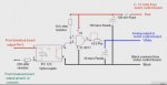
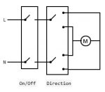
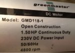
I have a treadmill motor (rated 1.5Hp, 4800 rpm, 230V DC) and controller which I can run from a picaxe pwm. The controller only runs in one direction, but I want to use it in reverse too. In my intended application, it will always stop for at least a fraction of a second before reversing, so I could achieve this using 2 spdt relays (as attached, also here https://quasarelectronics.co.uk/media/ecom/images/reversible-dc-motor-using-2-relays.gif), on the power leads to the motor, controlled from picaxe output pins. The whole device is for microprocessor controlled lifting via a screw jack basically, but it's operation isn't critical safety wise, ie nothing physically dramatic would happen if it failed.
The relays shouldn't be a problem electrically if grafted into the existing wiring, although I supect I may only find relays with 12V coils suitable for this kind of load?
Which brings me to my question. How should I calculate the Voltage/Current rating needed for the relays? Any suggestions as to where to buy something suitable? I'm thinking Farnell, mouser, etc etc, or ebay if the quality isn't an issue there.
Thanks
Attachments
-
 11 KB Views: 18
 ... or make a high voltage H bridge... good luck...