Has anyone here used the Sparkfun 434MHz RF modules with any M2 PicAxe?

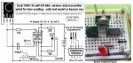
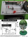
I'm new to the PicAxe and I've never worked with any RF communications before so I was hoping somebody here might have some tips about using Sparkfun's 434MHz RF modules or something similar to them:

www.sparkfun.com/products/10534
www.sparkfun.com/products/10532


EDIT: NOTE: Please see post #59 of this thread for the solution to my problem with these Sparkfun units


I've been using a 14M2 PicAxe on both the transmitting and receiving ends using rfin and rfout and, of course, it doesn't work right away, so I'm now in the process of debugging my set-up. But while I do that, I was hoping somebody here might have some tips or tricks on what to beware of.

One question: the Sparkfun forums suggest that the transmitter needs to be running all the time for the receiver to lock onto it, but I also get the impression the Manchester encoding would eliminate that requirement. True?

Also, just to be sure I'm doing this right, would the following line of code work for the transmitter?

Code:
RFout  B.1, ("Success!")
And for the receiver on a different PicAxe?

Code:
RFin  C.0, b0, b1, b2, b3, b4, b5, b6, b7
Thanks
 
Last edited:

Technical

Technical Support
Staff member
These should work, please post the entire programs you are trying to use at each end, plus details on exactly how each module has been wired up.
 
These should work, please post the entire programs you are trying to use at each end, plus details on exactly how each module has been wired up.
Hi Technical,

I'm pasting the programs for both the transmitter and receiver. It will take me a while to get a schematic drawn up but I will get around to that soon.


Code:
;RF.TX.Test1d
;25 SEPT 2012


;This program is designed to work with the 14M2 PicAxe
; to test the SparkFun 433 MHz RF transmitter.


;Pin B.1 will send the signal to the RF transmitter. 
Pause 1000 ;Wait for transmitter to power up. 

Main:

  RFout B.1, ("Success!")
  Pause 2000 ;Wait 2 seconds 
  
GoTo Main

Code:
;RF.RX.Test1a
;24 SEPT 2012


;This program is designed to work with the 14M2 PicAxe
; to test the 433 MHz RF receiver from SparkFun

;Physical Pins 2 and 13 will be occupied by the Serial com for Debug.
;Pin C.0 (Physical pin 7) will read data coming from the RF receiver.


;Start a loop to watch for data on Pin C.0 ...
Main:

;The program hangs until RFin receives 8 bytes of data...
RFin C.0, b0, b1, b2, b3, b4, b5, b6, b7
Pause 100 ;Wait a little.
Debug ;View variables on the PC.
Pause 1000 ;Wait 1 second


GoTo Main
When I power up both units, my Debug window opens up and says it is "waiting" but all the boxes remain blank.
I have 0.1 uF ceramic and 10uF electrolytic caps on my power rails on both ends.
The transmitter runs off 4.5 volts, same battery pack as the PicAxe to which it is attached.
The receiver is powered by a benchtop power supply at 5.0 volts, which also powers the PicAxe on that end.
If I connect my Oscope to the transmitter antenna, I see spikey looking pulses around 2.5 kHz.
The PicAxe feeds signals to the transmitter that look nice and square, and these are also around 2.5 kHz, yet it's hard to tell the frequency since the signal train jumps around as I suppose the encoding is changing or the PicAxe is looping.

I'll post the schematic once I get it drawn up.

Thanks.
 

russbow

Senior Member
Have another look at the Sparkfun device sheets that you linked to, particularly the note about no identifier and the noisy band.

I have successfully used similar modules but have found syncing the Rx and Tx critical. There are lots of threads on the forum so a search might be useful.

My test routines are:-

Transmit

Code:
[B]#picaxe18m2[/B]

b0=0

do

	gosub sendit
	sertxd("Sent= ",#b0,cr,lf)
	pause 5000
	b0=b0+1

loop


sendit:

high c.2
SerOut c.2,T600_4, ("UUUUUUUUUUUUU") 'wake up Rx
pause 5
serout c.2,T600_4,($AA, $BB, $CC,b0) 'Output data
low c.2

return
Note the U's to wake up the Rx and the $AA,$BB,$CC qualifier.

.......and for receive

Code:
[B]#picaxe20m2[/B]

symbol ANT=c.0
symbol LCD=b.7


let b1=0

serout LCD,N2400,(254,1,254,1)
pause 200

do

gosub getit

b1=b1+1


loop


getit:
setfreq m4
serin ANT,T600_4,( $AA, $BB, $CC ),b0
pause 5000
setfreq m16
serout LCD,N2400_16,(254,128,"Count ",#b1,"   ")
serout LCD,N2400_16,(254,192,"Rcd = ",#b0,"   ")
return
Note that the string of U's are not considered but the $AA, $BB,$CC tell the Rx to get the following data.

Hope this steers you in the right direction
 
Have another look at the Sparkfun device sheets that you linked to, particularly the note about no identifier and the noisy band....
russbow,
I presume you are talking about this notice they have on that webpage:

These modules are indiscriminate and will receive a fair amount of noise. Both the transmitter and receiver work at common frequencies and don't have IDs. Therefore, a method of filtering this noise and pairing transmitter and receiver will be necessary.
I was hoping that the PicAxe Manchester coding on the RFin/RFout would handle that kind of problem, but based on your detailed comments, I'm getting the impression that RFin and RFout will not work with this sort of RF module. Is that your experience? Many thanks for providing your insights and all the code examples, etc. I'll probably try your approach late tonight and see if it works on these modules.
 

russbow

Senior Member
I maybe have thrown you a red herring as I have never used Manchester coding. With the 10s of bytes I have needed to transmit, I have found the preamble / qualifier route to be OK. Never tried the RFin / RFout. Guess it's something I should look at more closely. Not sure it's relevant to these pretty dumb devices though.Maybe your requirements are more stringent. Be interesting to see how this thread develops.
R.
 

eclectic

Moderator
Bit messy at the moment, but.

Cheapo tx/rx pair

28X2 tx powered by pin B.6
Transmitter from B.7

(See M.2, p. 199)


20M2 receiver pin B.7

Code:
;Forum  25/09/2012
;http://www.picaxeforum.co.uk/showthread.php?22213-Has-anyone-here-used-the-Sparkfun-434MHz-RF-modules-with-any-M2-PicAxe&p=217602#post217602
;
#picaxe 28X2
;power to tx from pin B.6
; TX on pin B.7

Main:

High B.6; Power transmitter

pause 1000
 
  RFout B.7, ("Vincero!")

  
  Low B.6 ; turn off power


  Pause 1000 
  
GoTo Main 


#rem
;TX
#picaxe 20M2

Main:
 
RFin B.7, b0, b1, b2, b3, b4, b5, b6, b7
sertxd (b0, b1, b2, b3, b4, b5, b6, b7)

GoTo Main
e
 

Attachments

Technical

Technical Support
Staff member
, I'm getting the impression that RFin and RFout will not work with this sort of RF module.
Actually this is exactly the type of module RFin/out are designed for.

On the receiver have you got ALL the 5V and GND pins connected - this is often necessary on these modules. Also note it's datasheet says min 4.9V, not 4.5V.

Make sure the modules are a good 2m or so apart - not too close.

We recommend transmitter V+ is switched on and off as in Ec's example above, not on permanently. This datasheet may help with ideas, the principles are the same:
www.picaxe.com/docs/axe213.pdf
 
...
Cheapo tx/rx pair...
Thanks, eclectic. I'm glad to hear it's at least theoretically possible to use these cheapo type of RF's with the RFin, etc. So maybe my wiring is bad or my particular modules themselves are more prone to noise. Which type of cheapy RF modules did you use for this, if you don't mind my asking?
 
Actually this is exactly the type of module RFin/out are designed for....
That's encouraging. Thank you.


On the receiver have you got ALL the 5V and GND pins connected - this is often necessary on these modules. ...
Yes, at least they appear to be connected. This is on a breadboard, so I guess I'll have to double check everything wire by wire.

...
Also note it's datasheet says min 4.9V, not 4.5V.
Yes, for the receiver, I have it at 5.0 volts. On the other hand, the data sheet for the transmitter allows for 4.5 volts, I believe.


We recommend transmitter V+ is switched on and off as in Ec's example above, not on permanently. This datasheet may help:
www.picaxe.com/docs/axe213.pdf
I originally had it set up that way, but there was a heap of noise on that power line, so I connected the transmitter power directly to the 4.5 volt "rail" and put my capacitors on that rail, too, to filter the noise. This was done just for debugging purposes.

Thanks for the ideas, Technical. It's nice to know it's worth struggling to get this working. For a while there I was worried that the RFin, etc. wouldn't work with this.
 

eclectic

Moderator
Thanks, eclectic. I'm glad to hear it's at least theoretically possible to use these cheapo type of RF's with the RFin, etc. So maybe my wiring is bad or my particular modules themselves are more prone to noise. Which type of cheapy RF modules did you use for this, if you don't mind my asking?
Similar to these:
http://www.ebay.co.uk/itm/RF-Radio-Wireless-Data-Transmitter-Receiver-433MHz-NEW-/320926426780?pt=UK_Gadgets&hash=item4ab8b4a69c

A couple of years old, so they may be slightly different.

To repeat Technical's question,
can you please post your schematic?

e
 

manuka

Senior Member
NoEinstein: These TX/RX modules are no doubt akin to dozens of similar cheap ASK (Amplitude Shift keyed) offerings. Check a typical layout & code from popular Keymark/Sparkfun offerings. I've recently given more refined US$5 Dorji ASK units a workout- check my heads up for possible ideas. While I've not knowingly used SparkFun's pairs, it'd be unusual if they DON'T work well under similar PICAXE control. However there are diverse things to consider-

* Your mains can be noisy (especially if a switched PSUs are in operation), so (initially at least) use a battery supply at both ends.

* The receiver supply must be very close to 5V. For trials, & to avoid organizing a regulator, perhaps use 3 x very fresh Alkaline AA (which usually have ~1.6V each new).

* The transmitter is usually happy however with anything between 3V-12V, but the higher supply may make the TX illegal ...

* MOVE THE TX WELL AWAY FROM THE RX -preferably across the room. The RX may otherwise become overloaded & desensitized.

* Local 433 MHz ISM activity (from radio hams, garage door openers, backyard weather stations, energy meters, car remotes) may flood the band. Grab a UHF scanner & check !

* Slower baud rates work best when the going gets tough- 1200bps & even 300bps are typical.

* Preambles are usually essential to awaken the RX (the "U" stream mentioned above sends multiple 01010101 = ASCII 85 for U), then perhaps even followed by a short (~5 ms) PAUSE.

* Qualifiers can be anything - ABC etc - & are handy when multiple senders are at work. However a noisy 433 MHz band may defeat this.

* Avoid t1200 etc "idle high" supply waste (t=true) by instead using n1200 (n=inverted) which idles low.

FWIW -global power limits of 10 or 25 mW (or less in the US ?) apply at 433 MHz. Most ISM activity is at 315 MHz in the USA.

Stan.
 
Last edited:
Well, I think I've found the problem (or at least one of the problems). When I power on the receiver, it places a +2.2 volt offset onto the line that goes to the PicAxe. I placed a 10K resistor between that line and ground and I still see this crazy offset even when no transmissions are happening. When it starts to receive, it then outputs to the PicAxe a squarish wave that has a peak around +4.2 volts and a valley around +1.8 volts. I considered using a voltage divider to get the highs and lows within range for the TTL input of the PicAxe, but the ratio math will not work out right. So I'm trying to think... could diodes be placed in series on this input line to trim off 1.2 volts or so? Is that possible? Would that be safe? Why in heck would there be an offset like that?
 
...These TX/RX modules are no doubt akin to dozens of similar cheap ASK (Amplitude Shift keyed) offerings. ....
Stan,
thanks for providing a great checklist for going over these things. Indeed, I found that getting away from the TX did clean up the display on the Oscope. Some weird harmonics or something starts to happen at close range. I'll look into those Dorji units you suggested. This thing I've got now apparently has problems of some sort.

Thanks again.
 
Well, I think I've found the problem (or at least one of the problems). When I power on the receiver, it places a +2.2 volt offset onto the line that goes to the PicAxe....
Oops, I was wrong about this. I was looking at the so-called Linear Output of the Receiver, which has this offset. The actual digital output has no such offset. Problem is, the digital output has tons of noise on it, while the Linear Output is relatively clean looking, except for the offset, of course. I'm going to try using the Linear Output by running it through a diode (to trim off some of the offset) and see if I can get a better signal from that.
 

manuka

Senior Member
"Tons of noise"= I STRONGLY recommend that you monitor your local 433 MHz band &/or use battery supplies! Stan.
 
"Tons of noise"= I STRONGLY recommend that you monitor your local 433 MHz band &/or use battery supplies! Stan.
Sounds like a good idea. What I find so strange is that the noise (which appears to be random sinusoidal waveforms) is present on the digital output of the receiver but not on its Linear Output. I would guess that the Linear output is the raw signal and that the digital output is the signal after it's been somehow processed. So, if that's true, why would I see sinusoidal crap on the digital output but fairly clean (though apparently chaotically spaced) trapezoidal waves on the linear output? It almost makes me think that the receiver is somehow adding noise to the signal before it lets it out of the digital output pin.
 

manuka

Senior Member
To repeat Technical's question,can you please post your schematic(s)?
A schematic is now indeed ESSENTIAL! With cheap digital cameras a parts layout pix should also be offered too. Even Windows Paint & a phone camera can rustle up something lucid - refer below

EXTRA: Although almost trivial, it just may be worth checking that your units ARE both on the same freq. It's not unknown for a 315 MHz TX to be accidentally mixed in with a 433 MHz RX !
 

Attachments

russbow

Senior Member
This thread has prompted me to look into the RFin / RFout commands.
Read the manual.
Read the AXE 213 PDF

First attempt >

error001.png

Have got a link working with 20m2's. So far not impressed. What advantage is there in using these commands over the preamble / qualifier route, and if these are still needed for "cheapo" Rx/Tx pairs why use Rfin, RFout.

Using this TX code

Code:
;Forum  25/09/2012
;http://www.picaxeforum.co.uk/showthread.php?22213-Has-anyone-here-used-the-Sparkfun-434MHz-RF-modules-with-any-M2-PicAxe&p=217602#post217602
;
#picaxe 20m2
;power to tx from pin B.6
; TX on pin B.7

b0=0

Main:

High B.6; Power transmitter

pause 1000
 
  RFout B.7, ("ABCDEFG",b0)

  
  Low B.6 ; turn off power


  Pause 1000 
  b0=b0+1
  
GoTo Main
and this RX code

Code:
#picaxe 20M2

symbol LCD=b.0

b8=0
serout LCD,n2400,(254,1)
pause 200

Main:

 
RFin B.7, b0, b1, b2, b3, b4, b5, b6, b7
sertxd ("Count = ",#b7,cr,lf)
serout LCD,n2400,(254,128,"Count = ",#b7,"  ")

sertxd("Loop  = ",#b8,cr,lf)
serout LCD,n2400,(254,192,"Loop  = ",#b8,"  ")

sertxd(cr,lf)
b8=b8+1
GoTo Main
I am getting >10% receive failures.
 

russbow

Senior Member
Separating the Tx / Rx by 20 metres reduced the failures to about 5%

Increasing the pause in the Tx code to 2 seconds and also adding a 10nF cap across the transmitter supply pins improved still further
I am now getting about 6 counts dropped in a loop of 255.
 
Separating the Tx / Rx by 20 metres reduced the failures to about 5%

Increasing the pause in the Tx code to 2 seconds and also adding a 10nF cap across the transmitter supply pins improved still further
I am now getting about 6 counts dropped in a loop of 255.
Very interesting results you have there. Your tests have inspired me to keep playing with this particular receiver unit, but I'm now working on the theory the unit has something fundamentally wrong with it, same as some other complaints I've read on the Sparkfun website comments. I've ordered another pair of transmitter/receivers from a different vendor, but in the meantime I'll probably try the "brute force" serial method of operating with these and see what happens.

Thanks for sharing the results of your tests with rfin and rfout. :)
 

hippy

Technical Support
Staff member
I'm now working on the theory the unit has something fundamentally wrong with it, same as some other complaints I've read on the Sparkfun website comments.
None of the comments on the Sparkfun site led me to believe there was something fundamentally wrong with the modules, transmitter nor receiver, but some of the commentators don't seem to have a lot of RF experience and seem to be expecting things which won't be.

If the transmitter is not sending a regularly changing bit pattern the receivers will most likely be showing noise. That's to be expected.
 

russbow

Senior Member
I don't want to highjack this thread but my test results may clear the fog a little.

I don't really know why one should use the RFin/RFout functions but I suspect it has to do with error checking. Adding sertxd to my original program

Code:
#picaxe 20M2

symbol LCD=b.0

b8=0:b0=1
serout LCD,n2400,(254,1)
pause 200

Main:

 
RFin B.7, b7, b7, b7, b7, b7, b7, b7, b7


sertxd ("Loop ",#b8,"  Num ",#b0,cr,lf)
sertxd ("Recd ",#b7,"  ",cr,lf)

serout LCD,n2400,(254,128,"Loop ",#b8,"  Num ",#b0)
serout LCD,n2400,(254,192,"Recd ",#b7,"  ")

b8=b8+1
if b8=255 then let b0=b0+1
endif

GoTo Main
I noticed that data was not being missed, but a zero was being received - easily missed with an LCD display as the digit was immediately overwritten.
I also noticed that when this happened, new transmission occurred straight away, no noticeable pause. The dump extract :-

Loop 0 Num 1
Recd 0
Loop 1 Num 1
Recd 1
Loop 2 Num 1
Recd 2

Loop 3 Num 1
Recd 0


Loop 4 Num 1
Recd 3
Loop 5 Num 1
Recd 4
and this is always the case.

Does this mean that error checking has caused a re-send. and will the faulty "packet" always be zero? If so, easily dealt with in the Rx software.
 
Last edited:

hippy

Technical Support
Staff member
Does this mean that error checking has caused a re-send. and will the faulty "packet" always be zero? If so, easily dealt with in the Rx software.
There won't have been a re-send from the transmitter as it's uni-directional, the receiver cannot tell the transmitter it did not get valid data.

Whatever the PICAXE is receiving it does seem some 'gibberish' was detected which caused the RFIN to see that as valid zero data. What happens probably depends on exactly what gibberish is received.

One can use some of the bytes of the data sent as qualifiers and checksums which can help reduce the number of invalid packets.
 

hippy

Technical Support
Staff member
Yep -

RfOut pin, ( $AA, $BB, $CC, b4,b5,b6,b7,b8 )

RfIn pin, b1,b2,b3,b4,b5,b6,b7,b8
If b1 <> $AA Or b2 <> $BB Or b3 <> $CC Then BadPacket
 

russbow

Senior Member
How about -

b8 = $60 XOR b1 XOR b2 XOR b3 XOR b4 XOR b5 XOR b6 XOR b7 ( copied from a working prog ! )

RfOut pin, ( b1,b2,b3, b4,b5,b6,b7,b8 )

............. but then how do I "un-xor" b8 at Rx end?
 

russbow

Senior Member
Ah, go through the XOR process with say b9 as target , and compare b9 with b8..:D
 
Last edited:

Technical

Technical Support
Staff member
These types of 'cheap' uni-directional transmitter/receiver pairs are normally used commercially to perform an action that gives visual feedback (e.g. opening a garage door), and the transmitter keeps repeating the signal over and over again until the button is released. So it simply doesn't matter if the odd packet or two is dropped.

No matter which PICAXE system is used (serout or rfout) you will always get the odd packet or two corrupt or lost, that's just the nature of these single direction radio devices. However for many applications that is acceptable. rfout is designed to send a preamble and manchester encode the data, so is more robust than serout, but is never going to give 100% tranmission packet success.

For a more robust system where data must be confirmed as being received you will always need a bi-directional device, such as an XBee or XRF or ERF module.
 
... rfout is designed to send a preamble and manchester encode the data, so is more robust than serout, but is never going to give 100% tranmission packet success.....
Technical,
Thanks for the info on what rfout does. For my application, it's somewhat like the garage door opener. I don't need a high success rate. Right now I think I just need a better receiver.
 

eclectic

Moderator
Technical,
Thanks for the info on what rfout does. For my application, it's somewhat like the garage door opener. I don't need a high success rate. Right now I think I just need a better receiver.
1. Have you got the schematic yet?

2. Have you tried the "traditional" way, with "UUU" etc.

e
 

manuka

Senior Member
NoEinstein: Mate- you are making this too hard for yourself (& us...)!!

* PLEASE POST A LUCID SCHEMATIC &/or layout pix. This is an absolute essential when trying to solve problems.

* Way back at post #3 a bench top PSU was identified as a possible noise culprit -have you tried a clean "5V" battery supply for the receiver yet ?

* Have you s-l-o-w-e-d the baud rate (to perhaps 300 bps)?

* Have you borrowed a scanner & checked for local 433 MHz band noise? (If a scanner is unavailable take the whole setup for a ride to a quiet rural area etc where urban 433 MHz activity should be greatly reduced). You may also care to make a "poor man's scanner" (see below- it uses little more than a RX module,NPN & a piezo)- these are invaluable 433 MHz setup aids. See =>http://www.youtube.com/watch?v=zsLmAJqSOr8&feature=relmfu

* The long accepted SERIN "UUU" preamble & "ABC" qualifier (with perhaps a short following pause) normally works a treat - have you tried this properly? Stan.
 

Attachments

HertzHog

Member
If one was using the ERF URF XRF type of modules to do this project...
Question a) Would no errors be seen as the transceivers do automatic error correction and repeat scrambled blocks etc. to give clean data.
b) Would the baud rate make no difference as it is just the serial chip interface speed as opposed to the radio one?
HertzHog.
 
1. Have you got the schematic yet?

2. Have you tried the "traditional" way, with "UUU" etc.
eclectic and Stan, I'm afraid I have to plead guilty of not yet drawing up a schematic. It's not that I don't cherish your expertise, but instead it's because I'm fairly convinced the problem lies with the receiver, and my wiring is fairly straightforward. Here's a summary of what I've observed:

When I look at the output of my bench top power supply on the Oscope, the voltage is 4.99 and its ripple is less than 3 mV.

The receiver has two output pins: a "digital output" and a so-called "linear output". For the purposes of my tests described below, I have neither of these pins connected to a PicAxe, but instead have each of them connected to its own 10K resistor whose other end is grounded. In other words, all my Oscope readings described below take place across a 10K resistor.

When I power up the receiver and leave my transmitter turned off, the receiver's "linear output" is a 2 volt mostly DC signal with a barely perceptible waver to it. (I live in a rural area, so I'm guessing the RF background noise isn't too bad - but so far that's just a guess).

Then, when I turn on the transmitter, the Oscope will show the receiver's "linear output" is dancing with trapezoidal waves that jump from about +1.8 volts to +4 volts or so. For the most part these waves look "clean" in the sense that there are no sinusoidal components in them. Their timing jumps around I think in response to the code coming from the transmitter. If I turn off the transmitter, these trapezoidal waves disappear and the "linear output" signal falls back to its stable 2 volt mostly DC signal. So far all of this seems logical to me: the "linear output" is exhibiting that the receiver is detecting signals from the transmitter when the transmitter is on, and the "linear output" is showing no signal when the transmitter is turned off.

Now, here's where I think things look fishy: with my transmitter still left unpowered and the receiver's "linear output" still looking nice and stable, when I check the Oscope reading of the receiver's "digital output" pin, there is a mess of sinusoidal and squarish-looking waves. The "digital output" is the output that the PicAxe is supposed to read, so it's obvious the PicAxe can't do its job if this "digital output" is dancing around even without any inputs. And, when I then turn on the transmitter, the mess of sinusoidal and squarish-looking waves seems to get somewhat worse, if that's possible.

I'm certainly no Einstein, but I can't figure out how the receiver's "linear output" could appear so well-behaved while its "digital output" acts crazy.... unless this receiver itself is junk.

Stan, your "poor man's scanner" looks fascinating. I can't wait to rig up one just to see what I can detect around here.

Where I've burned up most of my time lately is trying to tinker with that cleaner-looking "linear output" just to see if I can get some useable signals out of it, but so far no luck. Even if I got something to work, it certainly would not be a "final solution" - just intellectual curiosity. I haven't tried the old-fashioned serial technique yet on account of my obsession with this linear output signal. I've ordered a different pair of RX/TX just to see (hope) this whole dang problem will evaporate once I plug in new components.

I've already learned a ton of things just reading all your suggestions and seeing your thinking processes in action on this problem. I greatly appreciate what y'all have written here, but I think I'm going to back burner this RX/TX thing until my new units arrive. Either that or I'm going to hack a wireless door chime just for fun and see what the signal behavior looks like on one of those.

Thanks again!
 

manuka

Senior Member
With today's cheap hi res digital cameras it's hard to credit that at least a layout pix can't be offered. Who knows what we may spot...

"Tunnel vision" is a common circuitry woe I've found, & a fresh view can often spot blunders the assembler had overlooked. I well recall once helping a student with a very involved (but no-go) logic layout. He was so deeply into the likes of NANDs, XORs & shift registers that he'd completely overlooked running a 5V supply to one of the ICs.
 

manuka

Senior Member
Try not to make it too late tonight else -ah- it'll be a tad DARK. Mmm- refer pix -please confirm that you DO have matching pairs!? Have you -ARGH!-altered the screwed slug's position ?
 

Attachments

Top