Hi,
Since starting this thread, I've followed the availability of the various components and have "recommended" the PAM8403 (as an Audio Amplifier) in several other threads. Prices (and particularly shipping) have risen somewhat, but some are still very reasonable and often shipping times have now improved. Therefore, here are some more details about the PAM8403 amplifier modules, but first a brief update on my experiences using it as a stepper motor driver. IMHO it makes an ideal driver for the "micro-sized" stepper motors, particularly in a PICaxe/Educational environment. The modules are low-cost and their operating voltage range of 3 - 5.5 volts makes them almost ideal for most PICaxe power supplies. Their MOSFET Output transistors have a very low output voltage drop, whereas the bipolar Darlington output transistors of many conventional stepper motor driver chips can "lose" literally one or two volts, which is a significant limitation with a supply of only 4.5 volts (or less).
The Stepper motors:
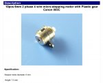
The motors in post #1 above have a diameter of 6mm and their "black" body is ferrite magnetic material which can be quite brittle. More easily available now are 8mm "silver" (metal) steppers which are stronger; I've measured their torque to be about 3 times higher, but with otherwise similar electro-mechanical characteristics (20 ohms per coil and 20 steps/revolution). They are sometimes described as having a "copper" gear, which at 2mm diameter is too small to find a convenient matching pinion, but can form an "axle" for small plastic gears, such as the "30/10/16" (pinions' teeth + thickness), available from Rev Ed (but their photo is misleading). These motors have their 4 terminal/pins almost in-line, which makes them rather more difficult to connect and mount on a PCB than my original motors, but some are available as pairs already-wired into a "loom" (my trial samples measured 40 ohms per coil).
PAM8403 Hardware Modules:
The PAM8403 chip is available assembled into various postage-stamp-sized PCB modules; some include a volume control pot., which adds to their size and cost, but is of no value when driving stepper motors, so I have not examined these. There are (at least) three styles of module, the most common "Green" type has 5 input pads at one end (Left , Ground, Right, Supply and 0v/Ground) and 4 output pads (L/R and +/-) at the opposite end. The pads have a 0.1 inch pitch, but not on a precise 0.1 inch overall grid. A "Red" style has all the connections along one side, but on a 1/14 inch pitch. A third style is described as "for Bluetooth" but does NOT have any Bluetooth functionality as such. These have pads on three sides, a Blue LED and a micro USB
Power input, with also pads for Power In
and separate Out (via a Schottky diode), mainly on a 0.1 inch pitch. The 3 styles differ in their implementation (or not) of the Standby (Shutdown) and Mute functions. Of particular interest may be the Standby function, because the quiescent power drain can be about 15 mA due to the PWM oscillator and any unbalance in the bridge output bias levels (the bridge requires no output coupling capacitor).
The PAM8403 should be used only with a "pure" Inductive load, because it delivers a modulated ~300 kHz "square wave" output which must be low-pass filtered to avoid large power losses (caused by any parallel Resistance or Capacitance). Also, the inductance is
essential as an energy-storage element, because Class D (PWM) amplifiers achieve their high efficiency by returning any "un-needed" current (energy) back into the supply decoupling capacitor (which may need to be quite large with low frequency audio). A small Loudspeaker or Stepper Motor winding may have a satisfactory inductance if connected by just a few cms of wire, but anything more should employ at least a ferrite bead on each wire (as recommended in the Data Sheet). However, ferrite beads add rather little inductance
(multiple passes of the wire through the hole may help but runs the risk of saturating the magnetic material), so an "air cored" helical (axial rod) inductor is preferable. Unfortunately, suppliers often omit to specify their (dc) resistance which should not be much over an ohm (perhaps a 22 uH) to avoid excessive voltage losses. In my experience a DC motor
will require series inductors, perhaps even to make the amplifier stable.
The PAM8403 manufacturer has issued at least two data sheets (dated 2007 and 2012) which indicate some changes in the design philosophy. Firstly, a "mistake" in defining the Standby (and Mute) inputs as "Active Low", with internal Weak (current) Pullups. The 2007 data sheet indicates the Standby current to be typically 50 uA, because the Pullup current must flow to disable the power! The later data sheet specifies a Shutdown current of less than 1 uA, but still refers to the presence of a Pullup current, which must now be very low (or non-existent?). The "Red" boards add an external pullup resistor (100k) for the Standby input (Mute is linked directly to the supply), the "Bluetooth" boards appear to leave the Mute input floating (Standby is linked to High), and the "Green" boards hard-wire both of these control pins directly to the power supply island. Perhaps this is the simplest option, because it's not too difficult to lift the relevant SMD pin(s) from the PCB using a hot soldering iron and knife-point, and then add a control wire if required.
Another issue is the amplifier voltage gain, noting that a Bridge Output gives a voltage gain of 2 (i.e. 6 dB) across the Load, but it's not clear if this is included in the specified +24 dB overall voltage gain (i.e. x 16). The (internal) schematic diagram indicates an "Op Amp" style voltage feedback (Virtual Earth at an inverting input pin), with an input/feedback resistor ratio of 15k : 85k followed by a gain of 1.4 = 8.0 (in 2007), or 18k : 142k followed by a gain of 2 = 15.8 (in 2012). The "Red" boards include an input potential divider of about 47K + 10k to define the gain, but the other boards use the Data Sheet application diagram with only an input 10k series resistor (and coupling capacitor). This suggests that a (limiting) Bridge Output from a Rail-to-Rail input (i.e. a gain of 2) requires an input series resistor of about 142k - 28k = 114k, but in practice the required value appears to be over 300k, which suggests that something is not as "expected", perhaps an internal buffer stage?
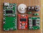
Here's a photo of an assortment of the components discussed in the text ("Bluetooth" board shown front and back).
 Using the PAM8403 as a Stepper Motor-driver:
The amplifier has only one input for each H-Bridge output stage (i.e. 2 pins), so a single 08M2 can potentially drive two stepper motors via a total of 8 pins, i.e. 4 coils (from pins c.0 , c.1 , c.2 and c.4). The input would be taken High or Low to drive current either Forwards or Backwards through the coil and Tri-stated (floated / set to input) or driven mid-level to switch the coil current off.
Note that C.0 can be configured as the "DAC" output and C.2 for PWM (followed by "light" Low-Pass filtering) which allows the PICaxe to apply a slight DC offset to the amplifier input. This can be useful to "brake" one of the motor coils where the load might otherwise drive the gear train in reverse (e.g. the winding drum for a crane hook) without driving the full coil current.
Normally, an H-Bridge will be Direct (Current) driven, so the width and polarity of the drive waveform is quite flexible, but the PAM8403 input has a capacitor-coupled (AC) input. This is because a typical "audio" signal swings slightly positive and negative relative to EARTH potential, whilst the input to the IC pins is internally biassed at half the supply voltage. If the input is driven by equal positive and negative pulses (number and width), then the voltage drop across the input coupling capacitor will remain reasonably constant. However, the (average) output from the PICaxe pins is effectively biassed at half the supply rail (assuming equal negative and positive pulses), so the simplest modification is to short-circuit (bridge or remove) the input coupling capacitors. This is particularly easy with the "Green" modules, because the relevant capacitors are at the edge of the boards, in the middle of each longer side (next to each 10k/103 resistor). Also, the separate Earth connection between the L-R inputs can be "re-purposed" for the Standby Input (as shown in the photograph). This can be driven by the "Input Only" pin (Leg 4 on most M2 PICaxes) by adding a 100k Pull-down resistor which is over-ridden by activating the Weak Pullup resistor on that leg (i.e.
PULLUP 8 for the 08M2).
The gain (amplification factor) of the PAM8403 is much higher than is needed for Vdd/2 pulses from the PICaxe, but it is desirable to slightly over-drive the input to ensure that the output voltage efficiently reaches the Supply and Earth rails. A series resistor of about 100k, or maybe higher, seems to work well between each PICaxe output pin and the PAM8403 input(s) and may be fitted directly onto the module's PCB. A flexible arrangement for the "Green" PCB version is to add two new input pins/pads along the edge between the "audio" and "power" groups. These would be coupled via each (100k) series resistor to the PAM8403 side of the coupling capacitors (not short-circuited), to give the option of "Logic Level" DC control inputs, or the original AC-coupled Audio inputs. Another method to avoid the need to short-circuit the input coupling capacitors (untested), is to connect two (equal) bias resistors (perhaps 10K) from each input pin to Supply and Ground, in addition to the series resistor from the PICaxe pin(s).
A description of programming the alternative drive waveform strategies for these stepper motors must wait for another post/thread.
Cheers, Alan.
")