Falconunknown
New Member
Hi.
I'm writing here, because i have been reading a lot of topics, and I can't still solve my problem (Sorry for my English... I'm not native).
I have a PICAXE-28 Starter Pack with the AXE027 usb and the PIC16F886 chip
Also, I have 3 AA batteries 1.5V (non-rechargable)
All items were bought in PICAXE webstore (www.techsupplies.co.uk).
The topics that I have read are:
http://letsmakerobots.com/node/7826
http://letsmakerobots.com/node/32933
http://letsmakerobots.com/node/25593#null
http://www.picaxeforum.co.uk/showthread.php?22022-Programming-Error-Hardware-not-found
http://www.picaxeforum.co.uk/showthread.php?21313-Newby-hardware-not-found-problem
http://www.picaxeforum.co.uk/showthread.php?22485-Hardware-not-found-problem
http://www.picaxeforum.co.uk/showthread.php?8905-Not-connecting-to-picaxe-chip
http://www.picaxeforum.co.uk/showthread.php?18915-quot-PROGRAMMER-NOT-RESPONDING-on-COM5-quot-problem
http://www.picaxeforum.co.uk/showthread.php?13305-Com-port-not-found-help-anyone
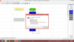
Well, my "issue" is: I cannot download any code to chip.
I decided attach some pictures... So, you can see what I mean.
Ohhh, almost forgot... My OS is Windows 7.
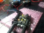
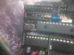
Chip = PIC16F886
Version Board = Red - Ed LTD 2001
Clip batteries test (3 AA // 1.5V) = 4.51V
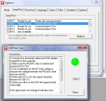
Plug Test (usb port test + led ON) = 5.16V
Plug Test (usb port test + led OFF) = 0.01V
Download circuit test

Pins test (following picaxe manual instructions: "TEST ON ACTUAL CHIP V+ and 0V pins with a multimeter")
(Pin # 8 - Ground ) // (Pin # 20 - Positive)

The Picaxe manual (pdf) says:
Download Checklist
PICAXE microcontroller
• Is the correct PICAXE chip correctly inserted in socket (I think it's ok)
• Is a PICAXE chip (not blank un-programmed PIC chip) being used (I think the website would not fool me, right?).
• Is a damaged PICAXE chip being used (chip has had over-voltage o reverse power supply applied) (I think it's ok, I always use 3 AA batteries alcaline 1.5V non-rechargable)
• Is a smooth 4.5V to 5.5V DC supply correctly connected. TEST ON ACTUAL CHIP V+ and 0V pins with a multimeter! (I think it's ok, the last 2 pictures show that)
• Is the reset pin connected to V+ via 4.7k resistor (18 / 28 / 40 pin chips) (I don't know)
• Is the correct 3 pin resonator connected if required (28 / 40 pin chips) (I don't know)
• Are the serial download 10k/22k resistors correctly connected. (I don't know)
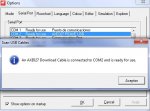
I have installed the usb controller, about two times... one from CD (.zip) and one from file of picaxe website (.exe).
I will hope that anyone can help me.
Thanks.
Jorge.
I'm writing here, because i have been reading a lot of topics, and I can't still solve my problem (Sorry for my English... I'm not native).
I have a PICAXE-28 Starter Pack with the AXE027 usb and the PIC16F886 chip
Also, I have 3 AA batteries 1.5V (non-rechargable)
All items were bought in PICAXE webstore (www.techsupplies.co.uk).
The topics that I have read are:
http://letsmakerobots.com/node/7826
http://letsmakerobots.com/node/32933
http://letsmakerobots.com/node/25593#null
http://www.picaxeforum.co.uk/showthread.php?22022-Programming-Error-Hardware-not-found
http://www.picaxeforum.co.uk/showthread.php?21313-Newby-hardware-not-found-problem
http://www.picaxeforum.co.uk/showthread.php?22485-Hardware-not-found-problem
http://www.picaxeforum.co.uk/showthread.php?8905-Not-connecting-to-picaxe-chip
http://www.picaxeforum.co.uk/showthread.php?18915-quot-PROGRAMMER-NOT-RESPONDING-on-COM5-quot-problem
http://www.picaxeforum.co.uk/showthread.php?13305-Com-port-not-found-help-anyone
Well, my "issue" is: I cannot download any code to chip.
I decided attach some pictures... So, you can see what I mean.
Ohhh, almost forgot... My OS is Windows 7.
Chip = PIC16F886
Version Board = Red - Ed LTD 2001
Clip batteries test (3 AA // 1.5V) = 4.51V
Plug Test (usb port test + led ON) = 5.16V
Plug Test (usb port test + led OFF) = 0.01V
Download circuit test
Pins test (following picaxe manual instructions: "TEST ON ACTUAL CHIP V+ and 0V pins with a multimeter")
(Pin # 8 - Ground ) // (Pin # 20 - Positive)
The Picaxe manual (pdf) says:
Download Checklist
PICAXE microcontroller
• Is the correct PICAXE chip correctly inserted in socket (I think it's ok)
• Is a PICAXE chip (not blank un-programmed PIC chip) being used (I think the website would not fool me, right?).
• Is a damaged PICAXE chip being used (chip has had over-voltage o reverse power supply applied) (I think it's ok, I always use 3 AA batteries alcaline 1.5V non-rechargable)
• Is a smooth 4.5V to 5.5V DC supply correctly connected. TEST ON ACTUAL CHIP V+ and 0V pins with a multimeter! (I think it's ok, the last 2 pictures show that)
• Is the reset pin connected to V+ via 4.7k resistor (18 / 28 / 40 pin chips) (I don't know)
• Is the correct 3 pin resonator connected if required (28 / 40 pin chips) (I don't know)
• Are the serial download 10k/22k resistors correctly connected. (I don't know)
I have installed the usb controller, about two times... one from CD (.zip) and one from file of picaxe website (.exe).
I will hope that anyone can help me.
Thanks.
Jorge.
Attachments
-
 472.1 KB Views: 16
 -
 52.9 KB Views: 14
")