H-bridge

adub

New Member
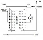
I was needing an h-bridge so I could reverse the direction of a Solarbotics GM3 motor. I was going to order a 293D but thought about using a ULN2003 like I've used for small unipolar stepper motors.

Would you take a look at the attached schematic? Surely it can't be that easy. The GM3 at stall draws 600mA so two outputs would be enough but why not hook up the rest of the pins too?

Any body tried this? I can't find my chips (cleaned out the spare room for guests and now can't find them) or I'd just breadboard it and see if any blue smoke comes out.

Thanks for any help.
Arvin
 

Attachments

Rickharris

Senior Member
The Darlington chip can only sink current i.e. current will flow into the device from a more positive potential so the motor can never have a positive supply.


You can build an h bridge with a few transistors, circuits abound, even here if you search or buy the L293.
 

BrendanP

Senior Member
H Bridges, a pain in the tokus.

Arvin, Ive done a bit of work with H bridges for a couple of application. I found them difficult to tame and probably for most apps more trouble than theyre worth. You get voltage drop through the transistors. If anything goes wrong with the timming of the switching on of the transsitors you get shoot through and at best a blown fuse or worse a melted bread board,pcb, wires or maybe a fire if you are unlucky. (or careless cause you havent used fuses).

I suggest you try using a DPDT relay for direction control and a mosfet for speed control. Use pwm on the mosfet so you can creep along the robot if you want. Turn off the mosfet before you switch the relay.

Obvioulsy it places great load on the motor and drive train to have instant high speed direction changes. Also by switching the realy with no current flowing through it you wont have any arcing on the contacts and thus the relay will be good for a huge number of cycles.

This soloution works well, try it.
 

goom

Senior Member
I'll second Brendan's comments. I've built a number of reversing speed controllers this way with up to 3A current draw. I have used latching relays to save power (just need a short pulse to turn them on or off).
Don't forget the diode across the relay coil to prevent back EMF destroying whatever you use to switch it on/off.
 

moxhamj

New Member
I agree. A high current automotive relay (12V coil) can work out cheaper than transistors (+mounting hardware, heatsinks etc). One mosfet (BUK555) direct drive from a picaxe (or one gate from your darlington) and a reversing relay with its BC547 transistor is a cheap option.

Strain on the drive train can be reduced by not switching directly from forward to reverse - in software you can ramp down pwm to 0, then switch to reverse, then ramp back up again.
 

adub

New Member
Found a couple of relays and my diodes and even a mosfet so I'll do it that way.

Quote from Solarbotics about the GM3: "This motor offers 50 in*oz of torque, rotating 360 degrees every 1.6 seconds (38 rpm - just a hair slower than a servo), at 5V, drawing 600mA at stall (free running at 52mA)."
Not exactly a high speed application.

It's for the extruder motor on my repstrap. I want it to stop instantly. I might not need to restart instantly. Until I get it running, who knows.

Thanks all.
Arvin
 
Top