PhilHornby
Senior Member
I have inherited a Solar PV installation that uses a Growatt 2500MTL-S inverter. There are nine panels, so the nominal output of the system is 2700W, but they are arranged in two banks, so they never produce maximum output simultaneously .
The Inverter has an RS232-C serial interface, accessed via a DB-9 plug from which data can be extracted. A WiFi dongle is available and Growatt provide an ecosystem for accessing this data. Aside from being quite pricey, this ecosystem appears to be based in China - not somewhere I willingly send my data!
Having obtained a manual detailing the protocol (attached), I set about building an interface. There is power available on the DB9 connector (+9V on "RI"), that is sufficient to power the Picaxe and attached HC12 Radio transceiver. I performed my initial experiments using Realterm on a PC and it soon became apparent that I had an issue to overcome...
The simplest documented interface mode, is where the Inverter is told to output data at a fixed rate. Unfortunately, it ignores the time parameter and just splurges out data continuously, with no gaps between packets. The start identifier of each packet is a "W" (0x57) character, which can also appear as part of the binary data - and so is useless for this purpose . I ended up looking for 4 null bytes that are always present and then reading the remains of that packet and the start of the next. Not ideal, but it seems to work
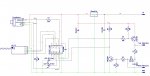
At boot-up (usually at sun rise), the Inverter is unstable and may have several attempts. Therefore, the code waits a minute before proceeding. The DB9 connector uses 'real' RS232-C signal levels, so level shifting is required. I could have used a MAX232-type IC, but thought it more interesting to 'roll my own'. (Actually, it's not my design at all, but is from a 'Serial Mouse' that was all the rage in the early 1980's!). See the code, for more details.
Acknowledgement to @AllyCat, for the use of his 'Divide31by15' routine.
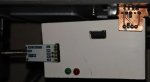
Physically, the board 'dangles' underneath the Inverter :-
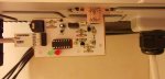
though it subsequently acquired a 'cover'. The 5V regulator is probably over-specced!
The Inverter has an RS232-C serial interface, accessed via a DB-9 plug from which data can be extracted. A WiFi dongle is available and Growatt provide an ecosystem for accessing this data. Aside from being quite pricey, this ecosystem appears to be based in China - not somewhere I willingly send my data!
Having obtained a manual detailing the protocol (attached), I set about building an interface. There is power available on the DB9 connector (+9V on "RI"), that is sufficient to power the Picaxe and attached HC12 Radio transceiver. I performed my initial experiments using Realterm on a PC and it soon became apparent that I had an issue to overcome...
The simplest documented interface mode, is where the Inverter is told to output data at a fixed rate. Unfortunately, it ignores the time parameter and just splurges out data continuously, with no gaps between packets. The start identifier of each packet is a "W" (0x57) character, which can also appear as part of the binary data - and so is useless for this purpose
. I ended up looking for 4 null bytes that are always present and then reading the remains of that packet and the start of the next. Not ideal, but it seems to work At boot-up (usually at sun rise), the Inverter is unstable and may have several attempts. Therefore, the code waits a minute before proceeding. The DB9 connector uses 'real' RS232-C signal levels, so level shifting is required. I could have used a MAX232-type IC, but thought it more interesting to 'roll my own'. (Actually, it's not my design at all, but is from a 'Serial Mouse' that was all the rage in the early 1980's!). See the code, for more details.
Acknowledgement to @AllyCat, for the use of his 'Divide31by15' routine.
Physically, the board 'dangles' underneath the Inverter :-
though it subsequently acquired a 'cover'. The 5V regulator is probably over-specced!
Attachments
-
15.6 KB Views: 3
-
196.9 KB Views: 4
Last edited: