Getting a count out of 08M ?

JBrookes

Member
Ive been building a glass blowing lathe. This kind of lathe has a head stock and tail stock that turn in unison to rotate the glass. My scheme has been to wrap an encoder strip around the HS chuck and read it with a photocell. I am using a neat little IC with a photodiode and transimpedance amplifier, OPA63, good to 14 khz. That will be fed to a 555 monostable circuit, then on to a picaxe 08 and on to a stepper motor driver board. The reason the 08 is in the loop is to take care of missing pulses from the encoder strip. It is difficult to get exactly 200 stripes around a steel disk, and the 08 can fill in any deficit, by counting pulses.

I am trying to determine best way to get a count out of the 08 during machine calibration..Perhaps the debug facility can do?
JB
 

eclectic

Moderator
Welcome to the Forum

What a fascinating project.

Firstly, could you provice a few circuit details
of the electronics you've built so far?

The sertxd function sounds the way to go for an initial readout.

e
 

bfgstew

Senior Member
Rather than have an ancoder strip on the chuck, fabricate a plate with 200 notches in every 1.8 degrees and use an optical sensor to 'see' the notches, should give you a more precise reading?

Stewart
 

boriz

Senior Member
Welcome to the forum.

How quickly will the chuck turn? (Realistic range of speeds)
Are you just trying to measure RPM or do you need an angular position sensor?
Will temperature be an issue?
What's your level of experience with electronics? With Picaxe? With programming?
 

JBrookes

Member
Hello
Ill try to make a generic reply

Here are replies to this post @@@
Welcome to the forum.

How quickly will the chuck turn? (Realistic range of speeds)
@@@ 30-100 rpm
Are you just trying to measure RPM or do you need an angular position sensor?
@@@neither - just synchrony between the encoder and the stepper. Measurement only at calibration time, to ensure synchrony. (glass gets liquid, so ends must turn together.)
Will temperature be an issue?
@@@ no
What's your level of experience with electronics? With Picaxe? With programming?
@@@quite a bit. optics also an issue. I've done quite a bit of programming, but not much picaxe sw. Ive used the photodiode ic before. The edge detection circuit easy. The mai challenge here is to get 200 pulses per rev coming out f the HS encoder setup.
The way I made the encoder is to go to a copy shop and piece together some striped patterns, then copy at various reductions. (89% etc.) Then I take a jeweller's loupe and .001 caliper to get stripes/inch. The idea is to get on the low side, say 195/rev, and let the 08 chime in at the end with the deficit pulses. (will involve getting a reading of pulse time width previously.)
The idea of making a 1.8 degree wheel OK, but how would you make it? Ideas about using commercial encoders OK, but have various problems. They are expensive, and would have to be attached by belt to the HS spindle. (direct drive blocks material entry.)
So my issue at this time is how to get a count of actual pulses so as to have the sw correct for the difference. Could be done with trial and error pretty easily though.

Now - I didn't say I was experienced in the motor area. Could this be done with servos more easily?

Thanks for all replies. As I said, the circuitry and sw fundamentally simple.
JB
 

bluejets

Senior Member
If you're still in the design and build stage, I'd be thinking more towards a common drive motor and sync belts (cogged belts)for the head and tail drive.
Many things to consider the way you are going that will catch you out further down the track.
 

Buzby

Senior Member
Hi JB,

I looked up some videos of these lathes.

The idea of a mechanical linkage between the stocks is not as easy as it looks, because they both can move separately along the track.

The RPM looks quite slow, so you would have no problem reading encoders, or even use stepper motors.

It does look like you could have an encoder ring on each stock, see the codewheel app for some software to make all kinds of encoders. See http://www.picaxeforum.co.uk/showthread.php?22560-IF-and-lookup-table-limits&p=222194&viewfull=1#post222194

I also saw the prices of these machines, I can see why you want to build one !.

Cheers,

Buzby
 

premelec

Senior Member
We used to use selsyns - basically a three phase transmitter and receiver motor so when one turned the other tracked it - I don't know what your torque requirements are or if selsyns are still available ['resolvers' were also used instead of encoders. I have some of this stuff in boxes somewhere... :) ].
 

JBrookes

Member
If you're still in the design and build stage, I'd be thinking more towards a common drive motor and sync belts (cogged belts)for the head and tail drive.
Many things to consider the way you are going that will catch you out further down the track.
I don't think a common drive motor is possible. ?
 

JBrookes

Member
the mighty 08 solves lathe synch

How do the commercially available machines keep in sync ?
Good question, Buzby. I have a friend with a glass lathe, and I'll ask him. I had assumed it was a mechanical linkage of some sort.

Here is the current solution I have come up with. There are two absolute light interrupters, one on head stock (HS) and one on tail stock (TS). Tostart the system, one puts the HS at top dead center, so that an led connected to the light interrupter is lit. Then a routine is triggered to turn the stepper on the TS until it too is lit. The device is ready to go! The main tracking routine is energized.
Now the HS motor is turned on, and the stepper keeps time with it, based on the encoder strip. The 08 waits until the HS does one rev, and its interrupter (LI) is lit again. Then begins the feedback correction routine. Say the
TS lags by 4 pulses. Then the routine calculates that it must insert an extra pulse every 50 pulses or so.
That's it! That's the feedback loop which prevents the device from drifting. Cybernetic feedback, a good principle of design here.
In this way, a precise encoder alignment is not necessary. The software handles it. The mighty 08 replaces a lot of mechanical hassle.
BTW, it should be mentioned glass lathes hold their work in graphite ring jaws, so are tolerant of slippage at startup.

My previous write-up, which will be a repitition:
The encoder plus light interrupters are a good way to go, I believe. The encoder handles routine synchronization, and the "top dead centers" keep the whole thing from drifting. The TDC indicators are classic feedback system.
The 08 will earn its keep with several routines:
-estimate timing of encoder pulses, and therby HS rpm's
-calculate "missing pulses" needed to add or subtract from pulse train to return system to synchronization.
-calculate places to insert or remove pulses. If 2 pulses are added, then add them at 0, 100. etc.
jb
 

JBrookes

Member
Selsyn motors:

Yes, I have a vague memory of seeing them someplace. Torque is nothing, just turns a 50 gram piece of glass against no load. The only issue with dual motors is we would be forced to use drive belts, since material must be fed into the lathe through the head stock spindle, making direct drive impossible.
My current solution is to use a direct drive stepper on the tailstock. The tailstock mounts on the lathe ways, and it holds the stepper which has its own chuck.
Thus the current HS motor is used, and the TS stepper slaves off it.
 
Last edited:

JBrookes

Member
Welcome to the Forum

What a fascinating project.

Firstly, could you provice a few circuit details
of the electronics you've built so far?

The sertxd function sounds the way to go for an initial readout.

e
"build?" You mean you actually do things here? :) Here are a few details, which may e a repeat of another post, if so my apologies:
I have built photodiode reader. I have made encoder strips.
The edge detector for the encoder is a 555 monostable trigger circuit. I decided to push it off the chip to keep sw on chip as simple as possible.
I got circuit from Doctronics website.
The 555 sends a pulse to the 08. It counts the pulse and emits a pulse to a driver board for the stepper.
That's it.
 

Buzby

Senior Member
... Then a routine is triggered to turn the stepper on the TS until it too is lit.
If you are definitely going to use stepper motors then you won't need an encoder at all, just a TDC mark on each stock.

To setup the initial positions the PICAXE drives both stocks to TDC.
From then on it just needs to send the same pulses to each stock, and the steppers will move in sync.
There is no need for the PICAXE to 'estimate missing pulses', there won't be any !.

I think you are going to need a bigger PICAXE.
You are going to struggle to get all the required control signals ( start, stop, jog CW, jog CCW, speed, etc. ) into an 08.

Cheers,

Buzby
 

SAborn

Senior Member
From what i seen in the Utube videos of glass turning in a lathe there is next to nothing in friction involved, so to use 2 suitable powered steppers running on the same instructions would be next to spot on.

Its no real difference than a CNC machine with X & Y movements, 99% of CNC dont have feed back and just rely on step commands sent to the motors.

If the steppers in a CNC dont have enough torque to step against the force applied, no amount of step correction will produce an good result.

From my understanding of this setup, it has an induction motor driving the main chuck through geared or belt reduction and the stepper needs to keep in sync on rpm with the chuck.

I know nothing about glass work but from what i seen in the videos, would it really matter if one end reached a 1/4 turn out of sync to the other in a worst case.

If this was exceptable i would use 4 magnets glued in position on each end, to rotate past a hall sensor each end, start the chuck spinning and have the picaxe adjust the tail stock stepper to match the rpm speed of the chuck, then light a Led to indicate rpm sync.

Go to work, and with the picaxe monitoring which sensor went high first (the chuck or stepper) and adjust the stepper to suit (faster or slower) as the rpm changed.

A dynamic system would have to be better than a chase me, catch me method, i would think.
 

bluejets

Senior Member
Well in that case, if it's an induction motor geared down to run the headstock and it runs as slow as they say, and 1/4 turn out is no problem, then just run another induction motor with the same gearing on the other end. Induction motors are frequency dependant as far as speed is concerned so the same motor each end should give the 1/4 turn sync needed.
 

Buzby

Senior Member
That may be ok in theory but what happens if one or the other slip, which does happen..??
Good quality steppers correctly driven within the limits defined in their datasheets don't slip.
That's not theory, it's the laws of physics !.

Steppers slip because of (a) poor drive electronics, (b) too high a speed demand, (c) excessive physical loading, and (d) software bugs.

If I was building this I would buy, ready built, the kind of steppers, driver boards, and PSUs used on CNC machines.
Then I would just need to concentrate on the PICAXE doing the control and display functions.

It looks like an expensive project, so skimping on the hardware is not going to save much money, but will give a lot of headaches !
 

JBrookes

Member
design feedback appreciated

Good quality steppers correctly driven within the limits defined in their datasheets don't slip.
That's not theory, it's the laws of physics !.

Steppers slip because of (a) poor drive electronics, (b) too high a speed demand, (c) excessive physical loading, and (d) software bugs.

If I was building this I would buy, ready built, the kind of steppers, driver boards, and PSUs used on CNC machines.
Then I would just need to concentrate on the PICAXE doing the control and display functions.

It looks like an expensive project, so skimping on the hardware is not going to save much money, but will give a lot of headaches !
@@@
Thank you all for the thought-provoking comments!
I happened to have a 7x10 minilathe with speed control, so have been focused on using its induction motor. However, putting a stepper in its place is an interesting idea.
The problem with the HS is that direct drive is out, as the stock needs to be fed through the hollow lathe spindle from the left side. As one commentator observed, linkages can slip, but I have a 5 hp
industrial cnc lathe with indexing control which uses a belt. As the commentator said, to paraphrase, you can just get rid of feedback complication by driving both ends with steppers. I believe that would be a 1:1 drive.
The drive pulley would fit around the spindle circumference and have the same dimension as the motor drive pulley wheel.
Thinking about it, I can find no catch-22 to this approach except for the trouble of setting up the pulleys.
About the rotation being 1/4 turn out, I think that's too much, but maybe not. The idea there was to just use say 4 points on the chuck body and synch up the TS based on them.
The problem I have with that is the startup phase - the TS won't know what the chuck is doing until a 1/4 turn has gone by, and meanwhile the other end of the glass is slipping in the TS chuck.
?
The expense is not that great. I have used a driver board.
Costs are approximately:
stepper - $20
driver board - $25
picaxe - $10
The components are low cost due to low torque needed here. I have a 18m picaxe, but using an 8 pin dip caught my imagination. :)

I had the lathe, which was a fixer I got from ebay for $300. This whole thing could be built without the lathe by essentially building a cnc router from scratch. The rigidity and strength of a metal lathe are not necessary.
But I'm avoiding that construction, though interesting to think about. Nearly any rinky dink construction would work here.

Thanks for comments. I am willing to turn on a dime regarding the design, as I have limited time, and anything that simplifies or reduces time demand, I'll go for. Fitting a pulley certainly seems easier than writing the feedback software, regarding driving both ends with steppers. Anyone see any deficit in this approach?
JB
 

JBrookes

Member
Thanks for comments. I am willing to turn on a dime regarding the design, as I have limited time, and anything that simplifies or reduces time demand, I'll go for. Fitting a pulley certainly seems easier than writing the feedback software, regarding driving both ends with steppers. Anyone see any deficit in this approach?
JB[/QUOTE]

@@@
I'll answer my own question...Suppose the drive is .2 % inaccurate. Then after 1000 turns, it will be off ("out of synch) by two full turns! If this drifting is a problem, it could be compensated for with a one-time calibration...or maybe not. A minor temperature diff in the pulleys could cause a cumulative error of some sort. Ordinary cnc lathes have these errors, but they are not important, since they are not continuously synch'ing two drives. The only machining operation where repeatable position is important is indexing for threading, and these lathes have expensive optical encoders, so long term drift is minimal.

Feedback and control is one of the most interesting areas of engineering, and that is where we are. My instinct is to use the stepper driver on both ends, calibrate one-time, but be ready to put an indexing magnetic/light sensor to give absolute feedback if necessary. What the stepper HS driver does, then, is get rid of the optical encoder band and its sensor - a good riddance if you ask me. Then the absolute indexer can be read occasionally to give feedback correction by inserting, dropping steps. So the essential feedback design remains the same, except we get rid of the encoder mess.
???
 

JBrookes

Member
A quick primer on feedback theory - aka Cybernetics

"Feedback and control is one of the most interesting areas of engineering, and that is where we are."

For those not familiar with this area, I'll give a quick history of it.

1. It is termed cybernetics, and was named by Norbert Wiener at MIT in 1949 time frame. He practically made a religion out of it, writing a number of popular books, worth reading.
2. the negative feedback loop is the center-piece of this idea - a sensor detects deviation and applies feedback in opposite direction to keep things on track. It's how we walk.

In engineering design, it makes sense to use it judiciously to push the need for precision out of the design. If the design elements can hold their precision over short time/space extents, then feedback can
occasionally correct things. In general, we may want to avoid real-time feedback AND long-term precision, as both are expensive of time and money.

Just a few thoughts for anyone interested.
 

John West

Senior Member
Interesting project. I used to operate a glass lathe, building CRT's for oscilloscopes, and got quite good at it, but all the while I never even thought about the synchronization between the head and tailstock. Now I feel ignorant.

Selsyn (I belive that's a brand name, not a generic name,) motors may have been the way our machines operated, though they are more likely used in applications where long term accuracy is necessary, (think mains operated wall clocks,) as their rotation was inherently phase synchronized to the AC line frequency.

While I suspect other synchronization methods are becoming more common today, there are still some Selsyn motors around in various industrial applications, and we have several at the surplus store where I help out. Interesting motors.
 

JBrookes

Member
How do the commercially available machines keep in sync ?
I will immediately call my friend with the 50k lathe and ask him. Frankly, I have deprecated this issue a bit, because:
-when the lathes were designed, they did not have steppers and picaxes, etc.
-the lathes are very expensive - a sign of inefficient design
-A mechanical design is inherently difficult, since the tailstock must keep rotating in step AND be able to move backwards and forwards at the same time. I am not a mechanical engineer, but this is
not "a walk in the park," design-wise. One way to do this, would be a shaft that runs longitudinally along the lathe bed, driven by the headstock motor. It has a pulley and belt that turn the tailstock chuck in unison with the HS chuck.
At the same time, the TS shaft is a spindle that is keyed to rotate, yet moves linearly....wow.
-I have complete confidence in cybernetic principles to achieve the end results here. Steppers, sensors, and picaxes are cheap.

I'll report back what he says.
 

JBrookes

Member
Interesting project. I used to operate a glass lathe, building CRT's for oscilloscopes, and got quite good at it, but all the while I never even thought about the synchronization between the head and tailstock. Now I feel ignorant.

Selsyn (I belive that's a brand name, not a generic name,) motors may have been the way our machines operated, though they are more likely used in applications where long term accuracy is necessary, (think mains operated wall clocks,) as their rotation was inherently phase synchronized to the AC line frequency.

While I suspect other synchronization methods are becoming more common today, there are still some Selsyn motors around in various industrial applications, and we have several at the surplus store where I help out. Interesting motors.
@@@ Yes, that's where my mind went when I initially thought about this design, but I could find no cases of current widespread use of selsyns today. One problem that this design faces is the issue of long-term drift. e.g., the chuck may rotate through 5000 turns, and even a small error can accumulate. I note that the specs for the stepper motors say "+/- 5%" on angle. We don't know what that means, but to expect two different stepper motors to remain in perfect synchronization over 5000 turns is probably unrealistic.
And that is where feedback and control comes in. It's very simple to put two optical sensors in place with a watchdog picaxe (chihuahua?) to coordinate things and apply corrective feedback. It just needs to chime in with an extra pulse or erase an occasional one. It's a lot of bang for buck, design-wise, imnsho.
 

JBrookes

Member
"How do commercially available machines keep in sync?" - Buzby.
I'll report back what he says.[/QUOTE]

I just talked with him, and he said the machines use a splined shaft running length-wise along the lathe bed. A belt drives the head stock, and also drives the splined shaft. On the TS end, a pulley rides along the splined shaft. It rotates with the shaft, but also can move longitudinally in the grooves on the shaft. They use metal belts of some sort, probably to allow the sideways movement of the moveable TS pulley. The chucks commonly used are based on graphite rings, which are tolerant of any slippage at startup. He also said the lathe has a electro-mechanical clutch to disengage the TS, not sure why.

He said these lathes are made in India, and retail around 12k for a small one - I haven't checked this price, since the $ is losing value rapidly...I'll report back if that price is incorrect.

That's about it. For me, I'd rather build from steppers than go the mechanical route. Just my leaning, but I'd rather use picaxe-cnc , than duplicate 19th century technology. I'm more interested in cnc than mechanisms.

Any thoughts?
JB
 

JBrookes

Member
"He said these lathes are made in India, and retail around 12k for a small one - I haven't checked this price, since the $ is losing value rapidly...I'll report back if that price is incorrect. "

I just checked, and the lathe has synchronous movement, but NO cnc - 12.5k. With accessories, that will be maybe 16k.
 

JBrookes

Member
I just talked with him, and he said the machines use a splined shaft running length-wise along the lathe bed. A belt drives the head stock, and also drives the splined shaft.

BTW, a "splined shaft" is a round rod with longitudinal grooves in it. This allows a pulley to turn with shaft, but also travel longitudinally.
 

Buzby

Senior Member
I note that the specs for the stepper motors say "+/- 5%" on angle. We don't know what that means, but to expect two different stepper motors to remain in perfect synchronization over 5000 turns is probably unrealistic.
"+/- 5%" means each step is up to 5% longer or shorter than it should be.
However, the steps per rotation is fixed ( 16 or 24 or 64 etc.) , so the total error after any number steps is 5% of the last step, not 5% of the total number steps.

Two, three, or one hundred identical steppers will stay in step, as long as all receive the same commands.

Actually, having such precise control of the sync using steppers may offer new possibilities for artistic experiments.
Maybe some 'twisty' effects could be created with controllable differential speeds between HS and TS.
 

JBrookes

Member
@@@ see comments below

"+/- 5%" means each step is up to 5% longer or shorter than it should be.
However, the steps per rotation is fixed ( 16 or 24 or 64 etc.) , so the total error after any number steps is 5% of the last step, not 5% of the total number steps.
@@@ Good. I believe the iron armature in the stepper has points, and it will not miss any (if conditions ok), except there is some indeterminicy about each step.
Do you know if all of these motors do partial (micro) stepping?
Two, three, or one hundred identical steppers will stay in step, as long as all receive the same commands.
@@@ OK But in my (our) evolving design, one of the steppers has a belt drive, and the other is direct drive. ISTM differences in belts, etc would create an error? Probably a fixed error, though. SO what you are saying, to extend it a bit, is that there may be no need for feedback here, since two 200 steps/rev wil always reach the same end-point, if driven by the same timing pulses. This keeps getting better.
Actually, having such precise control of the sync using steppers may offer new possibilities for artistic experiments.
Maybe some 'twisty' effects could be created with controllable differential speeds between HS and TS.
@@@ I'll have to ask the "creative department" about that, after we sober them up and dip them in dilute clorox. :)
 

bfgstew

Senior Member
Just thought I would chuck my thoughts in.
It should be relatively simple to make the HS and TS to run in unison using a stepper motor, it's getting it move along the bed axis that will cause the most problems with backlash and misaligenment.

GLASS1.JPG

The set up for the sliding pulley would simply be a pulley mounted on a hollow shaft that fixes into a bearing housing like a plumber block that is then bolted to the bottom of the TS, the drive shaft then slides through the hollow shaft, this will give rotation and axial slide. If you wanted it to be moved via another motor, add a leadscrew into the TS and drive it via a second stepper motor, use a couple of solid ground guide rods along the axis to give stabilty and guidance, should be a breeze!!!!!!!!
 

Buzby

Senior Member
I may be wrong, but I got the impression that the horizontal movement was not motorised.
It seemed to be completely manual, to compensate for the glass tube shortening or lengthening as various waves and wiggles were created.
So it should be reasonably straightforward to move one of the stocks on guide rails with a rack and pinion.

Slightly OT:, see the first exhibit here http://www.bbc.co.uk/news/science-environment-20339454 for what can be made with blown glass.
 

bfgstew

Senior Member
I agree with you Buzby, but, worth a punt. Just have it on a jog button, forward / reverse bring it into the 21st Century???!!!!!
 

boriz

Senior Member
Ive been building a glass blowing lathe. This kind of lathe has a head stock and tail stock that turn in unison to rotate the glass. My scheme has been to wrap an encoder strip around the HS chuck and read it with a photocell. I am using a neat little IC with a photodiode and transimpedance amplifier, OPA63, good to 14 khz. That will be fed to a 555 monostable circuit, then on to a picaxe 08 and on to a stepper motor driver board. The reason the 08 is in the loop is to take care of missing pulses from the encoder strip. It is difficult to get exactly 200 stripes around a steel disk, and the 08 can fill in any deficit, by counting pulses.

I am trying to determine best way to get a count out of the 08 during machine calibration..Perhaps the debug facility can do?
JB
200 stripes would be excessive IMHO. If I've worked it out correctly that's one pulse every 3mS @ 100 RPM. If you are using properly rated and driven steppers, the chances of them getting out of step are low, and certainly far lower than would require such frequent updates. It could also pose a challenge to the low speed of Picaxe BASIC. I'm thinking you could get away with as few as one pulse per rev. But lets say 8.

So @ 100 RPM, one 'sync' pulse every 75mS, 45 degrees. Much easier.

So how many pulses per rev of your stepper? Let's say for sake of argument 200. That's 50 pulses per 45 degrees.

A single Picaxe with two optical inputs and two stepper pulse outputs should be able to do the job thus:

When input1 is triggered before input2, it means stepper 2 has missed at least one of the previous 50 steps. So the pulse train from output2 needs to speed up a little or the pulse train from output1 needs to slow down a little, until the inputs are synced again.

The easiest method would be to slow down the faster stepper. It could be as simple as just missing a pulse. And if they are still not synced after the next 45 degrees, the slower stepper misses another pulse etc.

So if one step is lost due to drag or whatever, it can be re-synced within 45 degrees. 90 degrees for two lost steps, 180 degrees for 4 etc.

Shouldn't be too hard in Picaxe BASIC. And you could probably use the same system with more optical feedback pulses per rev. Say 16 or 32. But don't go crazy. Picaxe BASIC is pretty slow.
 
Last edited:

JBrookes

Member
200 stripes would be excessive IMHO. If I've worked it out correctly that's one pulse every 3mS @ 100 RPM. If you are using properly rated and driven steppers, the chances of them getting out of step are low, and certainly far lower than would require such frequent updates. It could also pose a challenge to the low speed of Picaxe BASIC. I'm tc.

I totally agree, even more so! I originally was concerned about slippage at at startup. That was the reason for the encoder + feedback. But now I see, heck, just run two steppers off the same pulse train and do a one-time compensation calibration. If there is any sync drift, then put in a single point light interrupter system for feedback, but unlikely to need it, as the lathe pretty much runs at a single low rpm. If I'm wrong, then single light interrupters would let the 08 chime in to keep the tune, so to speak.

I think its just great to avoid work! I'll drink to that! :) 
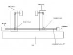
So the only issue now is to make a few brackets to hold steppers, mount pulleys, and devise bearings for the TS chuck. Tonight I was looking it over and looks possible. Luckily I have a machine shop at hand to make those custom parts...I plan to weld the brackets, as that's the quickest way to make them. The TS bracket is clamped to the quill which moves back and forth with TS hand wheel. This clamp may be trickiest thing to make. Current idea is to make a close-fitting clamp from 3/8 steel and use a threaded bolt to clamp it...or just use set screws. This clamp has to bear the weight of the stepper is all. Try set screws - easier to make.

I did talk with friend who has one of the lathes, and he said there can be slippage at atartup with no great bad effects, but I doubt we'll even have that. The traditional lathe chucks are made from graphite rings, and they hold the piece loosely. I'll make those rings later.

At this point, the 08 is just a one time calibration compensator. The idea is to get the two wheels in sync with hand turning at first. Then run it for a minute and check for slippage. Then modify picaxe program to compensate for that. If the thing cannot hold sync, then think about adding a single light interrupter on each side with 08 tracking things.

JB
 

BCJKiwi

Senior Member
A bit late to the party.
Do you need the power feed on the saddle?
If not, you could easily replace the threaded shaft that drives the saddle feed with a shaft with a single long keyway (a cheap spline).
Fit a gear over over it that drives the TS chuck.
A simple bracket off the TS chuck will guide the TS drive gear along the new shaft.
If you can find a gear set that will run the shaft at a suitable speed you could retain the saddle feed gearing else it will need to be replaced with a drive system to match the TS.
Job done (and you can use the lathe you are about to canabalise to make most of the parts).

You can still use the manual drive on the saddle as it runs off a separate rack.
 
Top