get schematic out of VSM into a post on this forum
- Thread starter Berny
- Start date
"Problems with the output" - What sort of output? The 555 circuit on pin 3? A vector drawing of your schematic in a standard format? A bitmap drawing of your schematic?
The easiest way to show your schematic here is to use the Print Screen key and crop it in Paint (Windows XP and earlier, and Linux) or use Snipping Tool (Windows Vista and 7) to capture your schematic and then upload the file. That will create a bitmap.
The easiest way to show your schematic here is to use the Print Screen key and crop it in Paint (Windows XP and earlier, and Linux) or use Snipping Tool (Windows Vista and 7) to capture your schematic and then upload the file. That will create a bitmap.
Last edited:
still unable to get a schematic posted
I did not explain the output issue as I am sure that a schematic will be needed. I assumed that being a Revolution software that it would be simple to "cut and paste" a schematic from VSM into a thread. There is a graphics output option but I have been unable to get it to work. I have created a schematic image as a bmp file however, when I attempt to put it in the thread, I get a red circle with an exclamation point and a message that says "invalid file". I attempted your suggestion with the same result. I assume it is something I am not doing correctly but I cannot find the answer. I hope this clarifies the problem and my reasoning for not fully explaining the output issue. Thank you for your reply and suggestion.
I did not explain the output issue as I am sure that a schematic will be needed. I assumed that being a Revolution software that it would be simple to "cut and paste" a schematic from VSM into a thread. There is a graphics output option but I have been unable to get it to work. I have created a schematic image as a bmp file however, when I attempt to put it in the thread, I get a red circle with an exclamation point and a message that says "invalid file". I attempted your suggestion with the same result. I assume it is something I am not doing correctly but I cannot find the answer. I hope this clarifies the problem and my reasoning for not fully explaining the output issue. Thank you for your reply and suggestion.
Does Proteus VSM look similar? PICAXE VSM is Proteus VSM with PICAXE chips.I did not explain the output issue as I am sure that a schematic will be needed. I assumed that being a Revolution software that it would be simple to "cut and paste" a schematic from VSM into a thread.
Use JPG!I have created a schematic image as a bmp file however, when I attempt to put it in the thread, I get a red circle with an exclamation point and a message that says "invalid file". I attempted your suggestion with the same result.
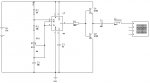
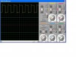
Finally got the schematic .. I think Now for the problem with the output. I am wanting to modify a 50Khz square wave to make a 50Khz sine wave. The circuit shown is supposed to accomplish this however, when I run the simulation, all I am seeing on the virtual scope is square wave with the tops and bottoms "malformed". The capacitor value is 180nF and the inductor is 56uH.
Again, I am probably not doing something correctly. Any suggestions?
Now for the problem with the output. I am wanting to modify a 50Khz square wave to make a 50Khz sine wave. The circuit shown is supposed to accomplish this however, when I run the simulation, all I am seeing on the virtual scope is square wave with the tops and bottoms "malformed". The capacitor value is 180nF and the inductor is 56uH.Again, I am probably not doing something correctly. Any suggestions?
Attachments
-
 40.3 KB Views: 33
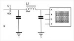
On the assumption that what you seem to have appears to be an integrator or series pass filter, I believe that what you need looks something like this, a low pass fiter to knock off the corners (high frequency harmonics). The inductor might be easily replaced by a resistor, which might be easier to change the value of.
Try this Low pass filter calculator
Enter a cutoff frequency, say 60kHz so that the second and subsequent harmonics are attenuated significantly.
Impedance, as you wish depending on your application, but 50Ohm is
Frequency response ripple. I guess at 0.5dB
Number of components, 3 for the Pi filter I have shown. This sort of circuit is good for transmitter outputs, so is probably good for you.
On the question of images: I use Linux and the drawing editor that I use exports .PNG files and my image was way too large for the forum. So I use the facilities of ImageMagick. Specifically the convert command, which just happens to be built into the Bash shell. IM is a cross platform program that will cost you nothing and is extremely powerful. Googling for the operations you want will give you a multitude of appropriate examples. It's available for Windows, so please give it a go, although I am unsure of the nature of the Windows interface.
From the Linux command line changing the type of an image and writing to a new file is as simple as:
convert mypicture.png mypicture.jpg
resizing an image:
convert mypicture,png -resize 30% mynewpicture,png
Resizing and changing the image type in one go:
convert Lpf.png -resize 30% Lpf.jpg
Nic12ab is absolutely right of course.
You might try connecting your C1 so that one end is to earth and the other end is joined to the junction of the two transistors as at present and the inductor there too.
A general rule of thumb that will get me into trouble with Hippy, Dippy, Manuka, WA55 and a few more no doubt.
When drawn in the conventional manner -
Plates of the capacitors Horizontal = low pass filter
Plates of the capacitors Vertical = high pass filter
With reservations:
The effective impedance of a given capacitor will increase as the frequency becomes lower. (the high frequency impedance may be affected by the type of construction (wound will have an element of inductance and electrolytic an element of resistance). As the frequency becomes DC, the capacitor is seen as an open circuit.
The effective impedance of of a given inductor will decrease as the frequency becomes lower At steady DC it is effectively a pure resistance and at high frequency can be seen as a brick wall. Manuka will tell you about "metal insulators" on parallel feed lines if you ask nicely . . . I kid you not.
Armed with those snippets of information you will make Dippy swoon (he will probably have a FET), but you will have an idea of what is going on. The descriptions I have given are of necessity simplistic and omit to mention phase changes, but that's making things more difficult.
I hope that if I haven't been helpful, then I have at least been mildly amusing.
Try this Low pass filter calculator
Enter a cutoff frequency, say 60kHz so that the second and subsequent harmonics are attenuated significantly.
Impedance, as you wish depending on your application, but 50Ohm is
Frequency response ripple. I guess at 0.5dB
Number of components, 3 for the Pi filter I have shown. This sort of circuit is good for transmitter outputs, so is probably good for you.
On the question of images: I use Linux and the drawing editor that I use exports .PNG files and my image was way too large for the forum. So I use the facilities of ImageMagick. Specifically the convert command, which just happens to be built into the Bash shell. IM is a cross platform program that will cost you nothing and is extremely powerful. Googling for the operations you want will give you a multitude of appropriate examples. It's available for Windows, so please give it a go, although I am unsure of the nature of the Windows interface.
From the Linux command line changing the type of an image and writing to a new file is as simple as:
convert mypicture.png mypicture.jpg
resizing an image:
convert mypicture,png -resize 30% mynewpicture,png
Resizing and changing the image type in one go:
convert Lpf.png -resize 30% Lpf.jpg
Nic12ab is absolutely right of course.
You might try connecting your C1 so that one end is to earth and the other end is joined to the junction of the two transistors as at present and the inductor there too.
A general rule of thumb that will get me into trouble with Hippy, Dippy, Manuka, WA55 and a few more no doubt.
When drawn in the conventional manner -
Plates of the capacitors Horizontal = low pass filter
Plates of the capacitors Vertical = high pass filter
With reservations:
The effective impedance of a given capacitor will increase as the frequency becomes lower. (the high frequency impedance may be affected by the type of construction (wound will have an element of inductance and electrolytic an element of resistance). As the frequency becomes DC, the capacitor is seen as an open circuit.
The effective impedance of of a given inductor will decrease as the frequency becomes lower At steady DC it is effectively a pure resistance and at high frequency can be seen as a brick wall. Manuka will tell you about "metal insulators" on parallel feed lines if you ask nicely . . .
I kid you not.Armed with those snippets of information you will make Dippy swoon (he will probably have a FET), but you will have an idea of what is going on. The descriptions I have given are of necessity simplistic and omit to mention phase changes, but that's making things more difficult.
I hope that if I haven't been helpful, then I have at least been mildly amusing.
sqaure wave to sine wave progress!
Paix,
Using your formulas I got different numbers for the components. C1 and C2 were 100nF and L1 was 174uH for 50Khz. I modified the 555 schematic but the waveform did not change! I created a new circuit using a 08M with PWM off pin 2 set for 50Khz and used the formula components and got a triangle looking waveform ... progress!
I was working from the schematics on this site, http://www.philohome.com/sensors/filoguide.htm. I am going to do some more testing until my new Oscope gets here next week and I can see what is really going on. Thanks Nick12ab and Paix for the help.
Sorry for the LONG delay, work, work, work. This is the circuit I was trying to put into VSM. Even wiring the circuit hardware up is not giving me a sine wave on mt DSO Nano scope. http://www.philohome.com/sensors/filoguide.htm
At the risk of hearing from no one, I am not interested in "how" it works as someone else has supposedly already figured that out and come up with a circuit which was published. I just want to use what someone else has done but as the VSM software is awesome, I like to put the circuit together in VSM before committing it to hardware. Right now, just a reply as to whether the link circuit is workable or not is all I am looking for. Thanks for your patience.
At the risk of hearing from no one, I am not interested in "how" it works as someone else has supposedly already figured that out and come up with a circuit which was published. I just want to use what someone else has done but as the VSM software is awesome, I like to put the circuit together in VSM before committing it to hardware. Right now, just a reply as to whether the link circuit is workable or not is all I am looking for. Thanks for your patience.