Hi,
The SSD1306 and SH1106 are "similar" Integrated Circuits for driving small OLED displays of up to about 128 x 64 pixels. These displays are of particular interest to PICaxe users because they are broadly compatible with most PICAXEs, being quite low-cost, using a supply range of 3 - 5 volts, a typical current drain of around 10 mA and a two-wire I2C bus capability. A forum search gives very few hits for the SH1106, but over 100 for the SSD1306, although many fail to reach a definitive conclusion. Fortunately, the data sheets for these two devices are available on the Web and reading both can be worthwhile to "fill in some of the gaps". For example the SH1106 data sheet makes a better attempt to explain when a $80 "Continuation" Control Byte should be used instead of a $00 Byte, although this still seems quite confusing (and maybe irrelevant).
The Data Sheets are quite complex, because the raw OLED display panels have almost 200 "connections", i.e. a multiplex with up to 64 "rows" (common/cathode) plus 128+ "columns" (segment) drivers, and then the microcontroller interface has another ~32 pins. Thus, the silicon dies have around 238 - 266 "pads" (in a maximum dimension of about 5 mm ! ). But fortunately, we don't need to work with (or can even see) the "naked dies" which are typically mounted directly onto a flexible "Kapton Foil" Printed Circuit Board via "Solder Bumps". These foils have an "Edge Connector" with a contact pitch of typically 0.7 mm to connect with either a microcontroller's full Parallel bus, or a Serial bus such as SPI and I2C. The foils are clearly visible at the rear of the 128 x 64 pixel displays and are separately available if access to the Parallel Bus (or some other features such as the Slave Address) is required. However, of interest here are the assembled Breakout Boards which bring out just the I2C Bus (4 pins) or an SPI (7 - 8 pins) interface onto a convenient 0.1" pitch header.
It should be emphasised that although the above modules are often described as having an "SPI / I2C interface", they are usually different modules, so it's important to select the correct type (i.e. the 4-pin I2C version). Sometimes the type of Controller chip is not specified and/or the two types may be described as "equivalent", but this is NOT correct. Their differences may be "hidden" inside an Arduino Library file, but they are important for a PICaxe user. Further care is needed because the header pinouts are NOT standardised, so the supply (Vdd) and Ground (Vss) pins may be found to be swapped (some boards even have moveable "zero Ohm" Vdd/Vss links). Both chips can be Hardware-Configured to either I2C Slave address $78 or $7A, but this is rarely a feature on the breakout modules, the majority being fixed at address $78 (or the misleading "7-bit address" $3C).
With both chips the "Display RAM" can be READ via the Parallel Data Bus, but NOT via the "Serial Interface" (SPI). It's arguable whether I2C is a "Serial" Interface, but the SDD1306 can NOT Read the Memory contents, but the SH1106 CAN READ the Display Memory via the I2C Data Bus. This is rarely discussed but confirmed in its Data Sheet and is particularly useful for the "Font in Program Memory" method which I devised for the 08M2 PICaxe, or to simply implement an active "Reversed Video" Cursor, etc.. Conversely, only the SDD1306 has additional internal Hardware to support some "Automatic" Scrolling features (Commands $20 - $2F), but only $20 - $22 appear to be in common use (see later).
Personally, I consider the 128 x 32 (0.91 inch visible diagonal = 23 mm) displays to be the more "useful"; usually a lower cost and able to accommodate 4 rows of 21 normal 5 x 7 pixels characters, emulating the ubiquitous "2004" LCD/OLED character displays (as used in the AXE134). Or a higher resolution font (up to 7 x 16) and/or greater character-spacing giving Double-Height characters can emulate the 2 rows x 16 characters of the popular "1602" displays (as in the AXE033/133 type modules, etc.). Also, these graphics displays have a full 1k of RAM, so it is possible to load a second field invisibly (in the background) and then "Pop" or "Scroll" the screen startline to change the display instantly.
If there is a specific need to display up to 8 rows of characters, the 0.96" (24mm diagonal) 128 x 64 displays seem "rather small", but the 1.3" (33 mm display diagonal) versions are sometimes not much more expensive. The two smaller displays (<1") appear to use mainly (or entirely ?) the SDD1306 chip, but a significant number of the 1.3 inch versions use the SH1106. That is how I come to be writing this note: I risked the purchase of a pair of 1.3" "unspecified" display modules from a Chinese seller (who has now updated his listing to indicate that they use the SH1106) which basically "did not work" with a functional PICaxe "SSD1306" Driver Program. Therefore, I examined the relevant Data Sheets and modified the Program Code, to the extent that it now seems "safe" to consider purchasing either of these chips, unless a specific "unique" feature of one of them is required.
A few more differences between the two chips: firstly the SH1106 drives up to 132 columns of pixels, compared with a maximum of 128 for the SDD1306. The former is arranged to map two inactive columns of pixels onto each side of the display, which might seem strange, but allows the horizontal scan to be reversed (i.e. Mirrored) without otherwise affecting the active pixels. Two pixels may seem an insignificant number, but they do represent almost half the width of a single 5 x 7 pixels character. However, the major difference is that the SSD1306 has three "Scan Modes", named "Horizontal", "Vertical" and "Page", (set by command $20 0x) whilst the SH1106 implements ONLY the Page Mode. This latter mode is also the "Default" (Power-Up) for the SSD1306, but the majority of the PICaxe threads have selected the Horizontal mode, making their code incompatible with the SH1106.
A "Page" mode may seem the most useful, but the term is used in the "computer" sense, not to describe a full displayed (screen) Page, but only a single horizontal Row of 128 Bytes (i.e. a band 8 pixels High). It is the Horizontal and Vertical modes of the SDD1306 which create a "Window" onto the whole screen, and that Window can be set to contain the FULL screen area. Thus the Horizontal Mode may be slightly more "convenient", particularly for character displays, but the Page/Row Addressing method should be familiar to users of character displays such a the 2004 and 1602, etc.: In principle, it is just necessary to adjust the Cursor's Column and Row Addresses at the end of every Row of character bytes. Therefore, I propose that all my future Program Code written for these displays will use only the Page Mode, to achieve compatibility between the various modules, as far as possible.
A common topic of the forum threads is the "Initialisation" of these displays, which can look quite complex, with long strings of obscure Byte values. However, the Data Sheets indicate that many of these commands are (usually) unnecessary, at least for the 128 x 64 displays when being started from a "Hard Reset" (i.e. after a Power-On). The controllers automatically initialise themselves with "Default" parameters to the extent that a SH1106 might need no more than a simple "Display On" command, i.e. HI2COUT 0 , ($AF) ! The SSD1306 needs also a "Switch Boost Power On", e.g. HI2COUT 0,(CHGPUMP, $14) , and the 32 line displays require some further hardware formatting commands. Then there are "User Options" such as "Mirror" (swap Left and Right), "Flip" (swap Top and Bottom), "Inverse" (swap Light and Dark) and "Brightness", etc.. Finally, it may be necessary to reload ALL the Default values, if corruption of the configuration may have occurred (by accident or intent) and a Hardware Power-Up is not convenient or possible. However, this does risk loading some "incorrect" values if the specific chip/hardware is not accurately known.
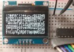
Since the SSD1306 cannot be Read via the I2C (or SPI) Bus, it is not possible for software to validate its type. A test of the I2C Bus's "Acknowledge" flag could check the Slave's existence on the bus, but it's probably easier to just run a Bus Search Routine. The SH1106 also doesn't have an "ID register", but the presence of its 1k of RAM at the correct Slave Address should give a good indication. Below, is a simple Test / Demonstration program to determine the controller type (between these two) and fill a 128 x 64 pixel screen with diagonal lines (two to exactly the NW and SE corners).
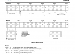
Reading data from the SH1106 did need some trial and error : Figure 7 in the Data Sheet indicates that the I2C Master needs to transmit only the Slave Address (i.e. HSERIN (data) , but this cannot discriminate between a Status and a RAM Read. In practice, it seems necessary to transmit also a Register number (e.g. HSERIN $40 , (databytes) to read the RAM, however, HSERIN $00 , (databytes) still doesn't appear to read the Status Byte. Also, as mentioned in the data sheet, it seems necessary to perform a Dummy Read, to skip the first received byte ("after the column address being set up"), so a typical input command becomes: HSERIN $40 , (@bptr , @bptrinc , @bptrinc ). To ensure that a specific RAM location is accessed, the Read-Modify-Write commands ($E0 .... $EE ) could be used to prevent auto-incrementing of the data pointer whilst Reading.
Yet again, I've exceeded the forum's 10,000 character limit, so must include the Program Code in my next post.
Cheers, Alan.
The SSD1306 and SH1106 are "similar" Integrated Circuits for driving small OLED displays of up to about 128 x 64 pixels. These displays are of particular interest to PICaxe users because they are broadly compatible with most PICAXEs, being quite low-cost, using a supply range of 3 - 5 volts, a typical current drain of around 10 mA and a two-wire I2C bus capability. A forum search gives very few hits for the SH1106, but over 100 for the SSD1306, although many fail to reach a definitive conclusion. Fortunately, the data sheets for these two devices are available on the Web and reading both can be worthwhile to "fill in some of the gaps". For example the SH1106 data sheet makes a better attempt to explain when a $80 "Continuation" Control Byte should be used instead of a $00 Byte, although this still seems quite confusing (and maybe irrelevant).
The Data Sheets are quite complex, because the raw OLED display panels have almost 200 "connections", i.e. a multiplex with up to 64 "rows" (common/cathode) plus 128+ "columns" (segment) drivers, and then the microcontroller interface has another ~32 pins. Thus, the silicon dies have around 238 - 266 "pads" (in a maximum dimension of about 5 mm ! ). But fortunately, we don't need to work with (or can even see) the "naked dies" which are typically mounted directly onto a flexible "Kapton Foil" Printed Circuit Board via "Solder Bumps". These foils have an "Edge Connector" with a contact pitch of typically 0.7 mm to connect with either a microcontroller's full Parallel bus, or a Serial bus such as SPI and I2C. The foils are clearly visible at the rear of the 128 x 64 pixel displays and are separately available if access to the Parallel Bus (or some other features such as the Slave Address) is required. However, of interest here are the assembled Breakout Boards which bring out just the I2C Bus (4 pins) or an SPI (7 - 8 pins) interface onto a convenient 0.1" pitch header.
It should be emphasised that although the above modules are often described as having an "SPI / I2C interface", they are usually different modules, so it's important to select the correct type (i.e. the 4-pin I2C version). Sometimes the type of Controller chip is not specified and/or the two types may be described as "equivalent", but this is NOT correct. Their differences may be "hidden" inside an Arduino Library file, but they are important for a PICaxe user. Further care is needed because the header pinouts are NOT standardised, so the supply (Vdd) and Ground (Vss) pins may be found to be swapped (some boards even have moveable "zero Ohm" Vdd/Vss links). Both chips can be Hardware-Configured to either I2C Slave address $78 or $7A, but this is rarely a feature on the breakout modules, the majority being fixed at address $78 (or the misleading "7-bit address" $3C).
With both chips the "Display RAM" can be READ via the Parallel Data Bus, but NOT via the "Serial Interface" (SPI). It's arguable whether I2C is a "Serial" Interface, but the SDD1306 can NOT Read the Memory contents, but the SH1106 CAN READ the Display Memory via the I2C Data Bus. This is rarely discussed but confirmed in its Data Sheet and is particularly useful for the "Font in Program Memory" method which I devised for the 08M2 PICaxe, or to simply implement an active "Reversed Video" Cursor, etc.. Conversely, only the SDD1306 has additional internal Hardware to support some "Automatic" Scrolling features (Commands $20 - $2F), but only $20 - $22 appear to be in common use (see later).
Personally, I consider the 128 x 32 (0.91 inch visible diagonal = 23 mm) displays to be the more "useful"; usually a lower cost and able to accommodate 4 rows of 21 normal 5 x 7 pixels characters, emulating the ubiquitous "2004" LCD/OLED character displays (as used in the AXE134). Or a higher resolution font (up to 7 x 16) and/or greater character-spacing giving Double-Height characters can emulate the 2 rows x 16 characters of the popular "1602" displays (as in the AXE033/133 type modules, etc.). Also, these graphics displays have a full 1k of RAM, so it is possible to load a second field invisibly (in the background) and then "Pop" or "Scroll" the screen startline to change the display instantly.
If there is a specific need to display up to 8 rows of characters, the 0.96" (24mm diagonal) 128 x 64 displays seem "rather small", but the 1.3" (33 mm display diagonal) versions are sometimes not much more expensive. The two smaller displays (<1") appear to use mainly (or entirely ?) the SDD1306 chip, but a significant number of the 1.3 inch versions use the SH1106. That is how I come to be writing this note: I risked the purchase of a pair of 1.3" "unspecified" display modules from a Chinese seller (who has now updated his listing to indicate that they use the SH1106) which basically "did not work" with a functional PICaxe "SSD1306" Driver Program. Therefore, I examined the relevant Data Sheets and modified the Program Code, to the extent that it now seems "safe" to consider purchasing either of these chips, unless a specific "unique" feature of one of them is required.
A few more differences between the two chips: firstly the SH1106 drives up to 132 columns of pixels, compared with a maximum of 128 for the SDD1306. The former is arranged to map two inactive columns of pixels onto each side of the display, which might seem strange, but allows the horizontal scan to be reversed (i.e. Mirrored) without otherwise affecting the active pixels. Two pixels may seem an insignificant number, but they do represent almost half the width of a single 5 x 7 pixels character. However, the major difference is that the SSD1306 has three "Scan Modes", named "Horizontal", "Vertical" and "Page", (set by command $20 0x) whilst the SH1106 implements ONLY the Page Mode. This latter mode is also the "Default" (Power-Up) for the SSD1306, but the majority of the PICaxe threads have selected the Horizontal mode, making their code incompatible with the SH1106.
A "Page" mode may seem the most useful, but the term is used in the "computer" sense, not to describe a full displayed (screen) Page, but only a single horizontal Row of 128 Bytes (i.e. a band 8 pixels High). It is the Horizontal and Vertical modes of the SDD1306 which create a "Window" onto the whole screen, and that Window can be set to contain the FULL screen area. Thus the Horizontal Mode may be slightly more "convenient", particularly for character displays, but the Page/Row Addressing method should be familiar to users of character displays such a the 2004 and 1602, etc.: In principle, it is just necessary to adjust the Cursor's Column and Row Addresses at the end of every Row of character bytes. Therefore, I propose that all my future Program Code written for these displays will use only the Page Mode, to achieve compatibility between the various modules, as far as possible.
A common topic of the forum threads is the "Initialisation" of these displays, which can look quite complex, with long strings of obscure Byte values. However, the Data Sheets indicate that many of these commands are (usually) unnecessary, at least for the 128 x 64 displays when being started from a "Hard Reset" (i.e. after a Power-On). The controllers automatically initialise themselves with "Default" parameters to the extent that a SH1106 might need no more than a simple "Display On" command, i.e. HI2COUT 0 , ($AF) ! The SSD1306 needs also a "Switch Boost Power On", e.g. HI2COUT 0,(CHGPUMP, $14) , and the 32 line displays require some further hardware formatting commands. Then there are "User Options" such as "Mirror" (swap Left and Right), "Flip" (swap Top and Bottom), "Inverse" (swap Light and Dark) and "Brightness", etc.. Finally, it may be necessary to reload ALL the Default values, if corruption of the configuration may have occurred (by accident or intent) and a Hardware Power-Up is not convenient or possible. However, this does risk loading some "incorrect" values if the specific chip/hardware is not accurately known.
Since the SSD1306 cannot be Read via the I2C (or SPI) Bus, it is not possible for software to validate its type. A test of the I2C Bus's "Acknowledge" flag could check the Slave's existence on the bus, but it's probably easier to just run a Bus Search Routine. The SH1106 also doesn't have an "ID register", but the presence of its 1k of RAM at the correct Slave Address should give a good indication. Below, is a simple Test / Demonstration program to determine the controller type (between these two) and fill a 128 x 64 pixel screen with diagonal lines (two to exactly the NW and SE corners).
Reading data from the SH1106 did need some trial and error : Figure 7 in the Data Sheet indicates that the I2C Master needs to transmit only the Slave Address (i.e. HSERIN (data) , but this cannot discriminate between a Status and a RAM Read. In practice, it seems necessary to transmit also a Register number (e.g. HSERIN $40 , (databytes) to read the RAM, however, HSERIN $00 , (databytes) still doesn't appear to read the Status Byte. Also, as mentioned in the data sheet, it seems necessary to perform a Dummy Read, to skip the first received byte ("after the column address being set up"), so a typical input command becomes: HSERIN $40 , (@bptr , @bptrinc , @bptrinc ). To ensure that a specific RAM location is accessed, the Read-Modify-Write commands ($E0 .... $EE ) could be used to prevent auto-incrementing of the data pointer whilst Reading.
Yet again, I've exceeded the forum's 10,000 character limit, so must include the Program Code in my next post.
Cheers, Alan.
Last edited: