FT232BL - USB to Serial Issue

tariq_niazi

New Member
Greetings,

I am new to this forum. I bought the FTDI FT232BL USB to Serial converter. Installed the drivers in both XP and Vista. Then I used the "Serial PIC Programmer" software downloaded from the PICAXE official website and tried to connect to the MCU but it gave me the error message (See Attachment). The FTDI is configured as COM Port 5 on my laptop. The PICAXE and the FTDI are both getting proper voltage.

Anyone can help me!

- TKN
 

Attachments

tarzan

Senior Member
AXE027

Take note that the AXE027 (FT232R) cable as supplied by Rev Ed is set with TX & RX inverted.


If you are trying to program a Picaxe in Pbasic then use the Programming Editor.
 
Last edited:

ylp88

Senior Member
You can also use FTDI's MProg application if you need to chance the inversion settings although make sure you save a backup of the original configuration so you can change back easily!

ylp88
 

tariq_niazi

New Member
You can also use FTDI's MProg application if you need to chance the inversion settings although make sure you save a backup of the original configuration so you can change back easily!

ylp88
Quick question, I am using a FT232BL and NOT a FT232R. Will this MProg work with FT232BL?

- TKN
 

ylp88

Senior Member
The FT232BM is listed as a device in the devices list of MProg 3.0 and I do believe that the FT232BL is simply the lead-free version of the FT232BM, therefore I would assume support.

Further:
MProg 3.0a - EEPROM Programming Utility said:
MProg has the ability to erase, program, read and read and parse the EEPROM contents for FT232R, FT245R, FT2232, FT232B, FT245B, FT8U232AM and FT8U245AM devices.
ylp88
 

hippy

Technical Support
Staff member
Then I used the "Serial PIC Programmer" software downloaded from the PICAXE official website and tried to connect to the MCU

The PICAXE and the FTDI are both getting proper voltage.
Not sure what you mean by "MCU"; are you trying to program a PICAXE or a PICmicro ?

If PICAXE you have the Programming Editor configured wrongly.

If PICmicro, do you have a BAS800 Programmer ?

Either way you shouldn't be needing to re-configure a standard USB to serial cable, especially one purchased from Rev-Ed.
 

tariq_niazi

New Member
Not sure what you mean by "MCU"; are you trying to program a PICAXE or a PICmicro ?

If PICAXE you have the Programming Editor configured wrongly.

If PICmicro, do you have a BAS800 Programmer ?

Either way you shouldn't be needing to re-configure a standard USB to serial cable, especially one purchased from Rev-Ed.
MCU = Micro Controller Unit

Well, first thing I tried doing before running the Programming Editor was running the Serial PIC Programmer to make sure it can communicate with the PICAXE using the FT232BL. Since that failed, I tried attempting to fix the problem but did not succeed. So now I will give a shot to the method of inverting the TX and RX signals as shown in the link above by tarzan on my FT232BL.

- TKN
 

tarzan

Senior Member
OK lets slow down a little.

First the “Serial PIC Programmer” is not for Picaxe use.
The “PICAXE Programming Editor” is what you want.
If your “FT232BL” is USB to RS232 then you won’t need to invert the TX & RX lines.
 

tariq_niazi

New Member
OK let me go slow also.

First I am using a PICAXE-08M.

I am running both Windows XP and Vista and have gotten the same check cable and power ... messages.

My screen shots for "Mode" and "Serial Port" tabs from the PICAXE Programming Editor are attached. I will post the screen shots for the properties window from the device manager tomorrow as I don't have a 5v DC power supply at the moment.

- TKN
 

Attachments

tarzan

Senior Member
OK now we are getting somewhere.

For power I would suggest using 3xAA batteries.
Please tell us if you are using a Rev Ed PCB, breadboard or other.
Your description of how you are making a serial connection is incomplete. It’s nice to know that you are using a FT232BL chip but that doesn’t tell us the whole story.
When plugging in and unplugging USB devices the PICAXE Programming Editor will have some difficulty keeping track of them so double check that your USB device is on the correct com port.
 

westaust55

Moderator
Also, did you download the FTDI drivers from the Rev Ed website.

My understanding is the standard Microsoft drivers will not work with the USB to serial cables for programming of the PICAXE chips
 

tariq_niazi

New Member
WOW, I have never seen such an active and fast responsive forum.

OK let me show what exactly I am doing.

First for powering the FT232BL and the PICAXE-08M, I am using a 5V DC from a power supply.

I am connecting all of this on a breadboard. See the attached picture for better understanding of how I did this. Basically the USB is connected to the FT232BL. From the FT232BL, the TX wire goes to the RX of the PICAXE-08M and vice versa for the RX to the TX. I have used the 10K in parallel with the 22K resistors as shown in the manual of the PICAXE on how to program them. Both are getting the 5V DC voltage from a power supply that can go up to 4A so current limitation should not be a problem.

As for the drivers, I am using the one's from the FTDI website and NOT the Rev Ed.'s website. Here is the link to the driver: http://www.ftdichip.com/Drivers/VCP.htm and using the 2.04.06 driver: http://www.ftdichip.com/Drivers/CDM/CDM 2.04.06 WHQL Certified.zip However, I also found this link today which has other driver related things I am not sure about: http://www.ftdichip.com/Documents/AppNotes.htm

Can someone please tell me the correct location for the driver that I am supposed to use from the Rev Ed.'s website?

- TKN
 

Attachments

eclectic

Moderator
Tariq. Two points:

1. "Parallel". ??
Please ensure that the download circuit looks like Manual 1, page 22

1. Downloads:

Scroll up this page.
"Software and Drivers"

Then, the USB drivers are near the bottom of the Software page.

e
 
Last edited:

hippy

Technical Support
Staff member
From the FT232BL, the TX wire goes to the RX of the PICAXE-08M and vice versa for the RX to the TX.
It may be worth swapping that so TX goes to TX, RX to RX but add a 180R is series with TX ( leg 7 ) the PICAXE first to prevent any damage.
 

tariq_niazi

New Member
OK after installing drivers from the FTDI website and from the Rev Ed website, still I have no success in connecting the Programming Editor to the PICAXE-08M.

The screen shot of the error I am getting is attached. Also the screen shots from the Device Manager are also attached.

I purchased this from eBay: http://cgi.ebay.com/ws/eBayISAPI.dll?ViewItem&rd=1&item=310062762885&ssPageName=STRK:MEWN:IT&ih=021 and NOT from Rev Ed as some people assumed that I have the AXE027 cable.

My driver info:
Driver Provider: FTDI
Driver Date: 3/13/2008
Driver Version: 2.4.6.0
Digital Signer: Microsoft Windows Hardware Compatibility Publisher

Like I have said before that I have tried both drivers from FTDI and Rev Ed website but no luck.

I have also switched the TX and RX wires to see if maybe I plugged them in wrong but still no luck.

I ran the MProg program also and have also attached the screen shot from it. Cannot read anything from it either.

Any help will be appreciated.

- TKN
 

Attachments

hippy

Technical Support
Staff member
I ran the MProg program also and have also attached the screen shot from it. Cannot read anything from it either.
Looks like the first hurdle to overcome is getting the cable to work. Until it does you'll be going nowhere with the PICAXE. Apart from removing and re-installing the FTDI drivers I don't know what to suggest. You could try and get it working on another PC, but I'm really clutching to straws.

Using FTDI drivers seem to be a case of it works or there's no end of problems. All the installations I've done so far have been completely painless, worked first time (98SE/XP)

That the unit is faulty cannot be over-looked. No reason it should be, but this is one of the risks one has to take with buying from companies which don't offer any technical support.
 

tarzan

Senior Member
Did you try the loop back test? As per the other on going post that is having some difficulty connecting to a Picaxe. Using just the FT232BL PCB connected to the PC connect TX & RX together. Open the Programming Editor select your com port open the “Serial Terminal” type something and see if it returns.

Now going back to my original post. If your FT232BL PCB TX & RX lines are not inverted as per the AXE027 cable from Rev Ed then you’ll need to place an inverter between the FT232BL & Picaxe or reconfigure the FT232BL.
 

tariq_niazi

New Member
Did you try the loop back test? As per the other on going post that is having some difficulty connecting to a Picaxe. Using just the FT232BL PCB connected to the PC connect TX & RX together. Open the Programming Editor select your com port open the “Serial Terminal” type something and see if it returns.
Yes, the loop back test worked I think. I used PICAXE->Terminal in the PICAXE Programming Editor then I typed testing and received testing back.

What is the use of adding <CR> at the end? Do I need it?

Also what baud rate is good for using with PICAXE?

- TKN
 

Attachments

Last edited:

tariq_niazi

New Member
I think I have found the problem. I followed the testing of the COM port and got a weird result. When the LED is turned OFF, I was getting the 5v DC when I should be getting 0v to -1v. And when I turned ON the LED, I got 0v which I should be getting a HIGH.

Therefore, I need to invert my signal. I have ran the MProg tool several times but the program option is turned grey.

Can I use an OP-AMP to invert the signal or follow so other way?

- TKN
 

Attachments

tarzan

Senior Member
This is good news your drivers are working.

CR = Carriage Return
LF = Line Feed

4800 with Sertxd

Now that we know the FT232BL is transmitting and receiving, will it be able to communicate with the Picaxe in its current configuration? If TX & RX are inverted just like the AXE027 cable yes, if not no.

Here's a good link: http://www.kpsec.freeuk.com/components/cmos.htm#4050
 

moxhamj

New Member
If it needs inverting you could use a single gate from a 74HC04 chip. Op amps can be used but they are not the best as many of them do not have outputs that go from 0-5V. Eg the 741 or 324 will only go up to 3.5V. So a logic gate inverter like the 74HC04 or 74LS04 or 74HCT04 would be the best.

But does it need inverting? Can I just ask - with no program being downloaded, what is the output? 0V or 5V or something else?
 

tariq_niazi

New Member
If it needs inverting you could use a single gate from a 74HC04 chip. Op amps can be used but they are not the best as many of them do not have outputs that go from 0-5V. Eg the 741 or 324 will only go up to 3.5V. So a logic gate inverter like the 74HC04 or 74LS04 or 74HCT04 would be the best.

But does it need inverting? Can I just ask - with no program being downloaded, what is the output? 0V or 5V or something else?
By output, do you mean on the TX or RX? On the TX of the FT232BL that is connecting to the RX of the PICAXE-08M, I am getting 5V or the VCC input voltage from the power supply. So basically that is a high when I first connect and turn on both of these devices. When I test the COM port and click on the LED to make it HIGH, it becomes ZERO or the TX of the FT232BL becomes LOW.

So with no program downloaded (since I cannot even connect to it properly yet), I am getting the input voltage of the FT232BL on the TX pin.

HTH.

- TKN
 

tarzan

Senior Member
After looking at your picture of Mprog it is confirmed that you have a FT232BM.

FT232BM does not support inverting the TX & RX lines but does support the RS232 BREAK setting and detection conditions.

So I am confident that you will solve this problem by placing an inverter between the FT232BM and Picaxe inverting both TX & RX lines.

Here are some excerpts from the manuals.

FT232RQ 32pin less (AXE027)

http://www.ftdichip.com/Documents/DataSheets/DS_FT232R.pdf

page 14

UART Controller with Programmable Signal Inversion and High Drive. Together with the UART FIFO Controller the UART Controller handles the transfer of data between the FIFO RX and FIFO TX buffers and the UART transmit and receive registers. It performs asynchronous 7 or 8 bit parallel to serial and serial to parallel conversion of the data on the RS232 (or RS422 or RS485) interface.
Control signals supported by UART mode include RTS, CTS, DSR, DTR, DCD and RI. The UART Controller also provides a transmitter enable control signal pin option (TXDEN#) to assist with interfacing to RS485 transceivers. RTS/CTS, DSR/DTR and XON / XOFF handshaking options are also supported. Handshaking is handled in hardware to ensure fast response times. The UART interface also supports the RS232 BREAK setting and detection conditions.
Additionally, the UART signals can each be individually inverted and have a configurable high drive strength capability. Both these features are configurable in the EEPROM.

UM232R

http://www.ftdichip.com/Documents/DataSheets/Modules/DS_UM232R_V103%20FT_000051.pdf

Page 9

UART Pin Signal Inversion - The sense of each of the eight UART signals can be individually inverted by setting options in the internal EEPROM. Thus, CTS# (active low) can be changed to CTS (active high), or TXD can be changed to TXD#.

http://www.ftdichip.com/Documents/DataSheets/DS_FT232BM.pdf

FT232BM

Page 6

UART
The UART performs asynchronous 7 / 8 bit Parallel to Serial and Serial to Parallel conversion of the data on the RS232 (RS422 and RS485) interface. Control signals supported by the UART include RTS, CTS, DSR , DTR, DCD and RI. The UART provides a transmitter enable control signal (TXDEN) to assist with interfacing to RS485 transceivers. The UART supports RTS/CTS, DSR/DTR and X-On/X-Off handshaking options. Handshaking, where required, is handled in hardware to ensure fast response times. The UART also supports the RS232 BREAK setting and detection conditions.
 

Attachments

tariq_niazi

New Member
Well I tried it using with NOT Gate (Inverter) and got the output working from the FT232BL using the test button. But still now it won't detect a PICAXE-08M. From the list of possibility of errors, I am suspecting it is # 3 or # 5 (See the attached picture). I am not sure what Error # 5 is saying.

However, after I checked the number listed (12F683) on the chip, I found out the following link: http://www.sparkfun.com/commerce/product_info.php?products_id=215 Can someone actually tell me what is the number on the PICAXE? I have read this thread and it shows that it is correct: http://www.picaxeforum.co.uk/showthread.php?t=6385&highlight=12f683 But mine also says I/P which I don't understand what its for? I am suspecting that this might be a blank chip since I bought it from some third party website.

I think they send me the wrong order. Now I will order PICAXE-08M from SparkFun and then post my result again.

- TKN
 

Attachments

Last edited:

hippy

Technical Support
Staff member
I checked the number listed (12F683) on the chip... I have read this thread and it shows that it is correct ... But mine also says 1/P which I don't understand what its for? I am suspecting that this might be a blank chip since I bought it from some third party website.
PICAXE-08M is a programmed 16F683 but what you have could be a blank PICmicro. The best way to check is to get a known 08M working then see if this 'shows some life' later, if not it could well be blank.

The 1/P is probably I/P, that's "Industrial/Plastic", the temperature rating etc of the component and the type of packaging it's in.
 

tariq_niazi

New Member
Well no luck yet. I have been very patient and should have never bought this stupid chipset (FT232BL). I bought two PICAXE from SparkFun and they don't work either. So far, the LED test passes and the ECHO from TX to RX works. But it still cannot recognize the PICAXE-08M :confused:

On my serial input pin, I have 3.4V. I have 5V source and the 10K and 22K resistors. Is that sufficient?

I am going to order the USB cable today, my last straw.

- TKN
 
Last edited:

tarzan

Senior Member
Ok let us go over this.
You have a working FT232BM with drivers installed.
You ordered some more 08M Picaxes from Sparkfun?
You have breadboard download circuit. (Consider buying Rev Ed PCB with this done for you.)

What is your 5volt power source?
Please post a wiring diagram that shows how you believe this should be connected. I would like to see your own work on this.
I still believe that this can work if done correctly.

P.S. I sent you an E-mail please let me know if you received it.
 
Last edited:

Hatman23

New Member
Hello

I`m have the same problem, i can`t understand this chip, don`t work for my how the Standar`s Serial Moden`s do, the signal channel is not inverted beacause the logic Voltage is the correct (VL). When testing my FT232BL show this parameter:

Supply with LDO CMOS 3v6

Logic State Port
TX (This port can change Status to TX# Logic 1 or 0)
Status Port is Open (connect to internal Pull UP Resistor (200k)) Logic 1
Status Port is Close (connect to internal Pull Down Resistor (200k)) Logic 0
Voltage Logic: 3.6v Status Higer (This Voltage make the Hig Level Logic)
State Port: Open

RX (This port cant change Status to RX# Logic 1 or 0)
Status Port is Open (connect to internal Pull UP Resistor (200k)) Logic 1
Status Port is Close (connect to internal Pull Down Resistor (200k)) Logic 0
Voltage Logic: 3.3v Status Low (This Voltage make the Low Level Logic)
State Port: Open

I think the port`s are inverter try with HC7404 Hex Inverter don`t work.

DTC-------74HC04-----DCE (FT232BL)
TX--------I/----\O-----RX

The logic Voltage of the RX Port change to 0.01 CMOS Low Level Logic the hardware are in line but the software is not (standars drivers can`t understand this state).

But work for inverter the Signal channel`s.

Try again with 74HC14 Hex Inverter with Schmitt Trigger Inputs don`t work. CMOS Low Level Voltage (Unkown Framing Error)

Try again with 74HC05 Hex Inverter with Open-Drain Outputs
High-Performance Silicon-Gate CMOS/TTL use Pull Up Resistor don`t work.
State port Low Z.

Try again with 74HC125 QUAD BUS BUFFERS (3-STATE) CMOS/TTL and work.
Connect VCC of the HC125 to LDO CMOS 3V6

DTC------74HC125---------DCE (FT232BL)
TX-------I/------\O--------RX

The imput voltage could be anything 2.5v, 3.0v, 3.3v, 3.6v or 5V. The HC125 everytime show in the logic output`s 3v6 max this is Hig Level Logic for FT232BL. Data incoming ok, no Framing Error`s, drivers worked fine.

But for transmit data i`m not find the correct IC.

Try transmit data to COM Port/Pc use 74LS244 OCTAL BUFFER LINE DRIVER(3-STATE) Low Power Schottky work for TTL Standard logic but not work for CMOS LOGIC.Try with 74HC244 OCTAL BUFFER LINE DRIVER (3-STATE) TTL ok CMOS not work
Try again transmit data to CMOS Level use 74HC125 QUAD BUS BUFFERS (3-STATE) not work.

I`m try again with 74HC4053 Triple 2-channel analog Multiplexer/Demultiplexer
when finish post result`s.

FT232BL no need Signal control or Flow Control but need DCD (Data Carried Detect) when the DCD State is Low Level Logic CMOS (0.01) RTS and DTR too, i`m connect Flow Control LoopBack RTS/CTS (Use 74HC125)don`t work (Drivers don`t work ERROR) DTR/DSR ERROR use Handshake and FullHandshake. Connect to RX DCD.
 
Last edited:

tarzan

Senior Member
Hi Hatman23
I do not have one of these FT232BL USB to Serial boards to test this on so I&#8217;ve only given advice that I believe should work; but maybe it does not work?
I&#8217;m posting a link that I setup for tariq niazi he gave no indication as to whether if he got his working or not.
 
Last edited:

hippy

Technical Support
Staff member
And people say life's much easier with USB ... ;-)

I re-read the entire thread to see if I could help but quite frankly I lost track of what the heck it is people even have as hardware let alone being able to tell what does and doesn't work, what tests prove what and so on. I'm truly impressed by tarzan's stamina here.

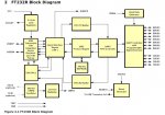
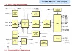
Using FTDI chips should not be hard; install the drivers, connect the hardware, run MPROG to configure the chip, and add inverters if the chip doesn't have the right output polarity and cannot be software configured. Connect to PICAXE, download, enjoy.

Obviously it's not that easy with all FTDI chips so the moral seems to be to buy official ready-to-use Rev-Ed USB cables, choose the correct FTDI chip model which can be configured as required for a PICAXE, or be prepared for having to sit down with datasheets to determine what must be done. It really does seem that trying to 'do it on the cheap' isn't necessarily cost effective in terms of time and effort.

I don't have much FTDI experience but here's how I'd go about it ...

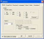
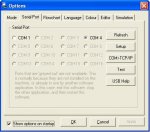
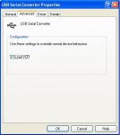
1) Download, unzip and Install the driver software

2) Connect the FTDI chip

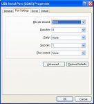
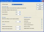
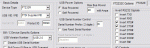
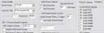
3) Run MPROG to turn off handshaking options

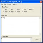
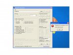
4) Connect TX to RX and get that working with the Programming Editor Terminal. What's typed should come back

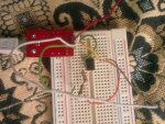
5) Connect a LED+R between FTDI TX and 0V and ensure that flashes on when data is sent . Use MPROG to adjust transmit polarity until that happens.

6) If the FTDI chip doesn't allow the signal to be inverted add a hardware inverter. Get the LED+R connected to that inverter output and 0V flashing on when data is sent

7) Connect the inverter output to FTDI RX. Check what is sent is what comes back using Terminal, adjust receive polarity using MPROG as necessary.

8) If MPROG won't allow that polarity to be changed, add an inverter to the RX as was done with TX. Connect the first inverter to the input of the second. Get that working so what goes out comes back using Terminal.

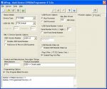
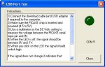
9) Run the Programming Editor Serial Test. Put a LED on the FTDI TX or its inverter if used. When the screen LED display is off, the physical LED should be off and voltage of the output should be near 0V. When screen LED is on, the physical LED should light and the voltage of the output should be near 5V or 3V3, whatever the FTDI power supply is.

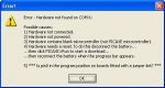
At that stage it should be working and usable to download to a PICAXE. If it cannot, something was over-looked in the earlier steps. Go back, repeat.

Of course, if it's not a PICAXE but a blank PICmicro download is never going to work.
 
Last edited:

hippy

Technical Support
Staff member
Also ... If anyone does want to build their own USB-to-Serial interface, the first place to start is the AXE027 manual. Rev-Ed were kind enough to provide a circuit diagram on the last page. Use the same FTDI FT232RQ and wire it as shown. If that works for Rev-Ed it will work for you unless you get something wrong. It may be necessary to use MPROG to configure the chip but it is self-evident that will be possible.

If you cannot use an FT232RQ use something which is *exactly* compatible; you'll have to do your own leg work to find what that is.

Choose something incompatible and expect there to be more work to do and more frustration in getting it to work.
 

ylp88

Senior Member
Note that when using the FT232R (I don't think you can do this when using the [older?] FT232B), you should not have to add inverters in order to set your correct logic levels. Whether positive logic (active high) ot negative logic (active low), FTDI's MProg utility should be used to configure these settings. It saves hassle and the possibility of a mistake.

The default settings look something like the picture below (I'm not sure about the states of the RTS# and CTS# signals, but it doesn't matter in this case anyhow...)
mprog_ft232r.gif

However, to program the PICAXE, you should be using the settings alike those used in the AXE027 cable:
mprog_axe027.gif

ylp88
 

hippy

Technical Support
Staff member
From the FTDI site, it appears this is the range of single channel USB to Serial chips -

FT8U232AM

Early generation product.

Seriously not recommended

FT232BM, FT232BL, FT232BQ

Second generation product. Can support external Eeprom (93C56/93C66) but without will require external inverters and possibly other handshake connections to be used with a PICAXE. Requires 6MHz crystal. 25mA normal operating current. All are compatible with each other.

FT232BM ( LQFP )
FT232BL ( LQFP, lead free )
FT232BQ ( QFN, lead free )

Not recommended

FT232RL, FT232RQ

Latest generation, super-set of the above BM, BL and BQ product. Includes Eeprom on-chip with configurable polarities. No need to use any external inverters. No external crystal required. Support component count reduced to minimum. 15mA normal operating current. Both RL and RQ are fully compatible with each other.

FT232RL ( SSOP )
FT232RQ ( QFN )

Recommended

Conclusion

For an easy life, use only FT232RL and FT232RQ and modules which contain them.

Using FT232BM, FT232BL and FT232BQ and modules which contain them is possible but require additional components.
 

Mookitty

New Member
Just a few questions regarding the FT232RL chip:

I've bought this breakout board: SparkFuns"s FTDI Basic Breakout and would like to know:

1) It currently does not work with my 14Ms, so do I need to invert the rx/tx signals using the info from post #37? (I am able to program the chips via serial, so the circuit is working. I'm bring out tx/rx/grd from the board, the other pins are unconnected.)

2) Is the inverting undoable, for "normal" use?

From reading the thread, I think both can be answered with 'yes' but I just want to make sure. Thanks for any and all help.
 

hippy

Technical Support
Staff member
1) Possibly it does need inverting. Run the Serial Test in the Programming Editor to see if the PC serial outputs are as or opposite to expected. Your TX/RX/0V conection is correct.

2) Using MPROG it should be possible to switch the inversion on and off at will. The FTDI device contains Eeprom which stores the setting so has a limited write lifetime but that's probably quite a few so should be no worry there - the manual should say.
 
Top