Fix a SENSOR-LESS MOTOR BLDC controller

Jacobsen

New Member
Is there anyone here who has experience with the coder to create a BLDC motor in a Micro Controller.

I am aware that there can be bought ready-BLDC controller.

But I would like to work with such a controller.
And to get good start then I have some questions below.

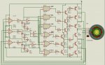
Which PIC circuit must be used
and has some coder and the circuit so I like to see engine running.
And then I would like to work with redirected coderne and Circuit.

Sincerely,
Monie
 

Andrew Cowan

Senior Member
The problem is that a PICAXE is not fast enough. Even overclocked, it would have trouble keeping up with the speeds of brushless motors. However, with a 20MHz PICAXE and a slow motor, it may be possible to putr something together.

A
 

jglenn

Senior Member
Brushless motor controls are a bear. There have been 2 installments of an article of how to do it in Servo magazine, Jan and Feb this year. Fred Eady is using a PIC18F2431, TC4428 drivers and NDS9952A fet chips. Programming in C.

The bridge kept blowing up, took him a half a day to find the code problem, but it works now. I use 3 phase motors in Eplanes, can get small 10A controls for about $20 from Hong Kong. But I prefer name brands like Eflite. This is one project I won't tackle!
 

Jacobsen

New Member
Hello All

It was not good, I could elles like to build a BLDC controller itself. Making a PCB
Eagle layout program.

Must only use one controller for BLDC
with max RPM 3500

But in saying PIC circuits not accept fast enough.

GO'Weekend

Sincerely,
Monie
 

InvaderZim

Senior Member
Excellent article by Microchip:

Sensored and Sensorless Brushless DC Motor Control with PIC

There are processor-less solutions available for sensored motor controllers that are quite easy to build; just take a few logic gates and FET drivers and wire the sensors up. Processor-less sensorless solutions have been posted on this forum, but I think have issues with startup. They use op-amps to observe back emf, but at startup I'm not sure how well it behaves.
 

tiscando

Senior Member
Invzim, this diagram I created is a sensorless commutator whithout a starter. Using zener diodes is one way of stepping down a voltage, but transistors and schmitt-triggers are possibly faster than zener diodes. There is a diagram of the schmitt-trigger way in my '3ph stepper motor spin...' thread, but the schmitt-trigger's inputs should be connected to the transistor's collectors rather than their emmitors, which are connected to gnd. I'll update that diagram and also create another example as soon as possible.

Edit: As to jglenn's post below, the initial circuits I've tried are only the first steps without any starting, so it's probably worthless trying them. I'm currently working on a brushless raw-PIC-based starter that uses EMF feedback from high-current pulses to sense the position of the motor.
 
Last edited:

jglenn

Senior Member
The Microchip ref is viable, but you must read the fine print. It says the motor must be moving at enough speed to generate the back emf feedback, for it to work. But all motors start from zero speed. In the controllers I have monitored on a scope, for up to 1/2 HP 3 phase model plane motors, drawing up to 60A at 12V, they do something interesting at start up.

Very short, high current pulses are applied to the windings, almost spikes. It won't go out of this mode until the rotor starts turning. There is some kind of current limit, too. These motors are funny. If you hold the prop with your finger, it won't start up. But once it's running, will chop off all the fingers without even slowing down. These scratch-built motor controls will cause you to spend a lot of money and time getting to work, take my word for it.

The drawing with the logic chips and bipolars is suicide, don't even try it.:(
 
Top