Fan speed controller

ashawthing

New Member
Hi, I am trying to create a system that will monitor temperature and adjust the speed of a fan accordingly. The fan I will be using is 12V, 6A dc.

I know how to monitor the temperature thats made easy with the use of the DS18b20 and readtemp but I am unsure exactly how to control the speed of the fan.

I've had a browse on here and it looks like I need to be using the pwmout command. Is it possible to add a variable in as on of the parameters and then have the temp reading adjust that variable up and down?

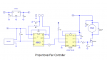
Also, could someone point me in the right direction with the circuitry I might need to power the fan?

Thanks
 

oracacle

Senior Member
yes it is possible, you would need to alter the period if i recall correcty, but its been a long while since i last worked with speed controlled motors and alike.

I cant help with driving at the minuite other than for the that sort of power you will need a hefty mostfet correctly driven to receive the PWM signal
 

Goeytex

Senior Member
Sounds like you want to make a proportional temperature controller

Example Schematic Attached.

You should be able to search the forum for "proportional" and find some example code for Proportional or PID control.

HERE is a code snippet I did a while back as an example for general proportional temperature control.

The DS18B20 / readtemp command is slow. (< 1 sample per second?), so see how that works out. May be OK for a fan.
 

Attachments

Last edited:

Circuit

Senior Member
Check out how your fan actually works. Many brushless d.c. fans have their own built-in drive circuitry that is not amenable to external speed control. Try running a variable voltage into the fan up to the rating voltage stated and see if it varies in speed proportionally; many won't, they just start up when a threshold voltage has been reached and then maintain a fixed-frequency driven speed. You need to know what you are working with to design the correct drivers.
 

DaveC166

Member
Ashawthing, you can alter the PWM duty cycle with the PWMduty command. use the Picaxe to Calculate what the duty cycle should be, load this into a variable and use this variables contents with the PWMduty command. Depending on the PWM freq a word variable may be needed. The PWM wizard is a quick way of checking this and the range of dutycycle.
In my case i use 10KHZ PWM on a 20m2 @4mhz. The dutycycle word variable ranges from 0(0%) to 400(100%), and can be altered in 0.5%( + or - 2) steps. I havnt tried 0.25% (+- 1).
 

neiltechspec

Senior Member
I found using varying pwmduty gave short breaks in PWM output every time the DS18B20 was read.

Using repeated pwmout didn't.

Also in my case, for the fan I'm using, the temp to pwm value was non linear for the fan speeds I wanted. So not easy to do a direct calc, hence my example in post 6 above.

I'm sure there are more code optimal ways of doing it, but as the 14m2 is not doing anything else, there is no point.

Neil.
 

ashawthing

New Member
Ok started messing around with this this evening. The fan is just a straight forward dc motor, there is no circuit built in so I guess this will make life easier. Could someone recommend what I could use to drive this thing? Are there FET's that are rated high enough to power this? Sorry my electronics knowledge is pretty limited. I also need an FET to drive 2 4" computer fans. They are also 12V but only about 0.2A
 

Goeytex

Senior Member
If you are not going to use a Mosfet Driver and intend to drive the MOSFET directly from the Picaxe ( questionable practice) then the IRL540 is a decent choice. It is a true logic level Mosfet and can handle up to 28 (de-rate to 20) amps of continuous current. With the low 2.5 amp current rating of your fan motor there is no need to use two FETs in parallel as neiltechspec did with his project. His project drew a lot more current.

Depending upon several factors, expect the FET an IRL540 to dissipate between 350mw to 1 watt at 50% duty cycle. These factors include switching speed and the value of the resistor between the Picaxe PWM pin and the gate of the MOSFET. Suggest you keep the switching speed at 1000hz or below.

With the circuit I posted, using a FET driver and the IRFZ46NL MOSFET...The FET will have to dissipate about 150mw. Yes, the FET driver costs an extra 1.20c, but it drastically improves efficiency ( less heat), reduces the load on the Picaxe, and provides some extra isolation between the Picaxe and the FET.
 

ashawthing

New Member
Thanks for all the help so far! I have now bot pretty much all the separate parts of this project working on there own, now I can start putting them all together to form the final product :) I do have one problem at the moment though. I am controlling the speed of the motor using pwmout which is working great. The only thing is that the motor is making quite a loud high pitched buzzing noise. Is there anything that I can do to reduce this? If I cant get rid of it then I wont be able to use this project
 

ashawthing

New Member
Ok, I managed to make the buzzing stop, I reduced the period on pwmout and it seemed to fix it.

I've now put all the separate parts together so I have basically finished this project (just need to solder onto a pcb and put in a project box)

I have a circuit that:
Measures temperature
Keeps a record of the minimum and maximum temps
Displays current, min and max temp on a 16x2 LCD display in real time
Controls the speed of a fan in proportion to temperature

I ended up using an IRL540N to drive the motor but I am noticing that it is getting very hot, far too hot to touch anyway. Would it help if I used two of them instead of just one? Or is there anything else I can do to reduce the heat? I have wired the motor straight between 12V and the drain, then connected the source directly to ground, is that ok?
 

lbenson

Senior Member
What is your pwm rate with the IRL540? Too high, and it will spend too much time in its linear region, which will cause it to overheat.

Can you control the fan sufficiently with a 1K rate? If so, does that help with the overheating?

Otherwise: heat sink, mosfet driver, multiple IRL540s, mosfet with specs more suitable to picaxe pwm driving.
 

neiltechspec

Senior Member
For your current draw, one IRL540 should be enough.

As previously asked, what is you pwm rate ?. Mine is 2khz & like I said they don't get warm running a 16amp fan @ 12v.

Mine does generate an audible whistle at lower fan speeds, but that doesn't bother me.

Do you have the FET mounted on a heatsink ?, mine are on 4" X 3" finned piece of 1/4" aluminium.

Mine does generate an audible whistle at lower fan speeds, but that doesn't bother me.

Neil
 

ashawthing

New Member
To be honest I'm not too sure what the pwm rate is, sorry I am a bit of a noob and just played around with different values to get the fan running where I wanted it. Most of the time though it will be running this command:

pwmout C.2,50,150

I haven't got a heatsink on it at the moment, I suppose that's a pretty obvious way of reducing the heat
 

neiltechspec

Senior Member
That is far too high.

pwmout C.2,50,150 is somewhere around 50% @ 20khz - that's why it gets hot !

pwmout pwmdiv4,C.2,124,250 is 50% @ 2khz

Neil.
 

ashawthing

New Member
Ok, just tried changing the pwm rate and it makes the motor buzz really loudly. Do you think it will be ok as I had it with a heat sink fitted or will it work the FET too hard?
 

neiltechspec

Senior Member
I would have said 20khz is way too high.

I wouldn't go much above 10khz (for heat reasons - got too hot for my liking), but I am not an expert in this area. Just learn't by experimentation & info on this forum.

Maybe a 'real' expert with pwm can advise further.

For me, 2khz noise is only noticeable at lower fan speeds and you can't hear it over the noise of a running V8 engine.
Fan speed slowly reduces to stopped when engine is turned off - dependant on radiator return temp, only lasts for a couple of minutes.

Neil.
 

lbenson

Senior Member
Ok, just tried changing the pwm rate and it makes the motor buzz really loudly. Do you think it will be ok as I had it with a heat sink fitted or will it work the FET too hard?
Try adjusting in steps down from 20khz to see if you can find a happy medium--acceptable noise and not too much heat.
 
Not that Iv'e done this project before. But being a master hvac technician I can tell you how I would do it. Use a X13 ECM motor you can pick up at any hvac distributor. Ask or research the exact model that uses pulse modulated control to run it at desired speeds. The ecm's usually have so much online data its almost miraculous. Using a temp probe that simply sends (I think 24vdc,via your circuit) to the motor you can have it go to as many cfm's as needed. thats what i would do... anyway.
 
Not that Iv'e done this project before. But being a master hvac technician I can tell you how I would do it. Use a X13 ECM motor you can pick up at any hvac distributor. Ask or research the exact model that uses pulse modulated control to run it at desired speeds. The ecm's usually have so much online data its almost miraculous. Using a temp probe that simply sends (I think 24vdc,via your circuit) to the motor you can have it go to as many cfm's as needed. thats what i would do... anyway.
...........actually to be cheaper I would get a 4 speed motor with 24 volt speed taps.... using low medlow medhigh high taps. using relays that were controlled by the microcontroller and simple temp statements like if b0 >120 then high b.1 (closing relay 1 for speed 1) etc.
they do come in 120v but mostly 240v
 
Top