john green
Member
Following through with my enquiry of a few days ago about using RTC's I thought it would be interesting to try and use 50Hz as a time source. As a test I have tried to achieve getting 30 second pulses to drive a vintage slave clock and now also a also a mechanical counter to confirm that the errors I am finding are originating from the circuit or program not the clock mechanism.
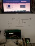
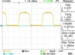
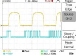
The circuit (illustrated below) is driven from an 8vac bell transformer with a very ordinary bridge rectifier, capacitor and regulator to get a 5vdc supply for the picaxe and a further adjustable regulator to get 1.4volts to drive the clock. (My counter is driven from an external power supply through an opto-coupler not included in the diagram). Half of an LM358 opamp is used to convert the incoming sine to a square wave form, this going to C.2 on an 08M2 to do some counting and supply a pulse output on C.4. The square wave is inverted from the sine wave and hence I am using the negative side of the square to equal the positive side of the sine (though I have tried un-inverted also just out of curiosity). I have included caps to eliminate any transients and looking closely with a scope, the wave forms and supplies are very clean and stable. The interrupt included in the code is to be able to fast forward the clock but this should not affect the present function.
The program originally counted 1500 inputs (30 seconds x 50Hz) and sent an output for the last two cycles - 40 milliseconds which perfectly suits the clock mechanism. The code in this form however consistently runs too slowly and an inconsistency of seconds is visible after only a few minutes using computer time as a reliable comparison.
Calculating the delay and resetting the values to count 1492 cycles for each 30 seconds results in an error in accuracy of a couple of seconds after seven hours (this being a consistent increase over that time so not likely to be the result of an occasional glitch) which error is anyway within what may occur due to mains frequency variations which I am aware of.
Confirming that the error is as shown by the validity of the alternative value of 1492, it is apparent that somewhere the program is losing 266us per second. I had expected that the way I had written the code and the speed of the processor would easily accommodate the time needed to achieve my intention within the much larger 20000us period of each cycle but I am very obviously wrong.
In the longer term, the inaccuracy of this is anyway going to accrue and I feel sure that this should work using the full 1500 cycles as the necessary measure.
Can you offer some pointers please as to what terrible error of judgement I have made...
Many thanks...
The circuit (illustrated below) is driven from an 8vac bell transformer with a very ordinary bridge rectifier, capacitor and regulator to get a 5vdc supply for the picaxe and a further adjustable regulator to get 1.4volts to drive the clock. (My counter is driven from an external power supply through an opto-coupler not included in the diagram). Half of an LM358 opamp is used to convert the incoming sine to a square wave form, this going to C.2 on an 08M2 to do some counting and supply a pulse output on C.4. The square wave is inverted from the sine wave and hence I am using the negative side of the square to equal the positive side of the sine (though I have tried un-inverted also just out of curiosity). I have included caps to eliminate any transients and looking closely with a scope, the wave forms and supplies are very clean and stable. The interrupt included in the code is to be able to fast forward the clock but this should not affect the present function.
The program originally counted 1500 inputs (30 seconds x 50Hz) and sent an output for the last two cycles - 40 milliseconds which perfectly suits the clock mechanism. The code in this form however consistently runs too slowly and an inconsistency of seconds is visible after only a few minutes using computer time as a reliable comparison.
Calculating the delay and resetting the values to count 1492 cycles for each 30 seconds results in an error in accuracy of a couple of seconds after seven hours (this being a consistent increase over that time so not likely to be the result of an occasional glitch) which error is anyway within what may occur due to mains frequency variations which I am aware of.
Code:
;read 50hz mains to get pulse out each 30 secs using 08M2

init:
setfreq M8
let W0 = 0

goto main:


main:
setint %00001000,%00001000     ; activate interrupt
if pinC.2 = 1 then goto main:
if pinC.2 = 0 then do
endif
if pinC.2 = 0 then pauseus 10
endif
if pinC.2 = 1 then goto pulse:
if pinC.2 = 0 then loop
endif

pulse:
inc W0
let W0 = W0 max 1492

if W0 = 1490 then high C.4
endif
if W0 = 1492 then low C.4
endif
if W0 = 1492 then let W0 = 0
endif
goto main

; Interrupt service routine
interrupt:   ;interrupt: loop here until the interrupt cleared
if pinC.3 = 1 then
high C.4 ; switch output 4 on
pause 80
low C.4
pause 500
endif

setint %00001000,%00001000 ; re-activate interrupt
return ; return from subIn the longer term, the inaccuracy of this is anyway going to accrue and I feel sure that this should work using the full 1500 cycles as the necessary measure.
Can you offer some pointers please as to what terrible error of judgement I have made...
Many thanks...
Attachments
-
 40.5 KB Views: 29
")