tonyengineer
New Member
I have a 28x1 operating and monitoring 8 solenoid valves, 2 air pumps, and indicator LEDs. When operating only the LEDs and solenoids, the program works fine. When the pumps operate the program is erratic, jumping back to the start, I assume resetting.
Both motors and solenoids are switched by two 2803s and the LEDs direct via 330Ω resistors.
I've been advised to put diodes and capacitors across the pump motors and twist their wires. I’ve also put pull down resistors on the motor 2803, I'm using 4 input/output coupled, to cover the current requirements for the motor and the chip gets warm, but not excessive.
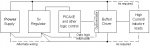
The power supply is 12v which operates the motor and solenoids, then through an inductor, 2 capacitors, 12-5v voltage regulator, and then another 2 capacitors.
The noise seen through a CRO attached to the last capacitor is quite spiky when the pumps operate, but after putting the caps on the pumps the program worked fine, then later starting failing again. I then tried other means also, wire twisting and inductor etc., again it worked, only to fail later.
I gather noise is transmitted through both the wiring and electromagnetic radiation with the PCB acting as a receiver. An earlier version of this, using a single pump and 08M still works fine, the pump is shielded from the Picaxe by a 1.6mm aluminium box, I assume this is helping.
Is it possible that the spikes are damaging the 28x1 making it less able to cope with the noise?
Any guidance or experience would be appreciated.
Both motors and solenoids are switched by two 2803s and the LEDs direct via 330Ω resistors.
I've been advised to put diodes and capacitors across the pump motors and twist their wires. I’ve also put pull down resistors on the motor 2803, I'm using 4 input/output coupled, to cover the current requirements for the motor and the chip gets warm, but not excessive.
The power supply is 12v which operates the motor and solenoids, then through an inductor, 2 capacitors, 12-5v voltage regulator, and then another 2 capacitors.
The noise seen through a CRO attached to the last capacitor is quite spiky when the pumps operate, but after putting the caps on the pumps the program worked fine, then later starting failing again. I then tried other means also, wire twisting and inductor etc., again it worked, only to fail later.
I gather noise is transmitted through both the wiring and electromagnetic radiation with the PCB acting as a receiver. An earlier version of this, using a single pump and 08M still works fine, the pump is shielded from the Picaxe by a 1.6mm aluminium box, I assume this is helping.
Is it possible that the spikes are damaging the 28x1 making it less able to cope with the noise?
Any guidance or experience would be appreciated.
")