Edge finding improvements

edmunds

Senior Member
Dear all,

Finally got some time for my little line follower again. I am now trying to optimise the code and one thing that was supposed to be easy is to rewrite the code so, that it would find the edges on the fly, without pixel data in memory first and retrieving for analysis later.

I have written the following piece of code which finds the leftedge correctly, but fails to find the rightedge. I cannot find a fault with the code, I think it should do what I intended it to, so I'm suspecting doing this between the CLK pulses varies the timing between the pulses too much and sensor just responds with garbage. Can you take a look and see if I'm missing something obvious? Suggestions for making this quicker are, of course, very welcome, too :).

Code:
Collect_data:
  adcsetup = 0

'/*Used to be a procedure call for read_data, now replaced with code for speed BEGIN
  high SI : pulsout CLK, 10 : low SI        'Pulse SI to end the scan/start the next scan
  pwmout CLK, 1, 4                                'Clock out some fast pulses (8MHz @ 64MHz clock speed
  pauseus Tint                                       'Allow for sufficient integration time
  pwmout CLK, OFF                               'Stop the clock
  high SI : pulsout CLK, 10 : low SI        'Pulse SI to end the scan/start the next scan
'/*Used to be a procedure call for read_data, now replaced with code for speed END

  leftedge = 0 : rightedge = 0                'Set both edges to zero
  for counter = 0 to 127                         'Read 128 pixels ...
    dat0 = pinAO                                      'Set dat0 the state of the pin - 1 for white, 0 for dark
  	pulsout CLK, 10                                  'Pulse the clock to go to next pixel
  	if leftedge = 0 then                             'In case line has not been found yet, look for set pixels for white
      if dat0 = 1 then                                 '... if the previous pixel is seeing the line (=1) ...
        dat0 = pinAO                                   '... set dat0 the state of the pin again ...
        if dat0 = 1 then                               '... and check the new, neighbouring pixel ...
          leftedge = counter                         '... in case two consecutive pixels are set, consider the left edge of the line
        endif
      endif
    else                                                     'If the left edge of the line is known, look for the right edge (set to clear transition) ...
    	if dat0 = 0 then                                '... do nothing about all the set pixels after finding leftegde, but stop for clear ...
    		dat0 = pinAO                                  '... set dat0 the state of the pin again ...
    		if dat0 = 0 then                              '... and check the new, neighbouring pixel ...
          rightedge = counter                      '... in case two consecutive pixels are clear, consider the right edge of the line
        endif
      endif
    endif
;    put counter, dat0                                'Store the value in scratch pad as one byte per pixel (to be changed to bits later)
  next counter                                         '... continue until done with all pixels
return
Thank you for your time,

Edmunds
 
Last edited:

eggdweather

Senior Member
I think you need to refresh dat0 with a dat0 = pinAO command first before starting the right-hand edge checks, otherwise dat0 is likely to be set and then fails the first test.

Or prefix the RH test with:
dat0 = pinAO 'Set dat0 the state of the pin - 1 for white, 0 for dark
pulsout CLK, 10
 

erco

Senior Member
@edmunds: Looking forward to seeing your line follower work. We need new content in the robotics forum! :)
 

edmunds

Senior Member
I think you need to refresh dat0 with a dat0 = pinAO command first before starting the right-hand edge checks, otherwise dat0 is likely to be set and then fails the first test.

Or prefix the RH test with:
dat0 = pinAO 'Set dat0 the state of the pin - 1 for white, 0 for dark
pulsout CLK, 10
Thanks,

Just before falling asleep I realised there could be more problems than that with the code. There could be two problems with the flow of the code - what happens just after the leftegde was found? Is the same cycle executed correctly to find rightedge? And, of course, one needs to exit the loop when rightedge is found, not continue looking for it through all 127 pixels. Will attend this later today as I need to do something else for now :).

Edmunds
 

hippy

Technical Support
Staff member
Your code seems overly complicated. One problem is using a valid 'counter' value of zero as a never set indicator for the 'leftedge' and 'rightedge' variables. That's going to cause problems when the zero reading is over a line and the 'leftedge' is set as zero which actually means not yet set.

You have two choices; either use something other than zero as the not detected flag or, better still adjust counter from 1 to 128 rather than 0 to 127 -

Code:
leftedge  = 0
rightedge = 0 
For counter = 1 To 128
  If pinAO = 1 Then
    ; Over line
    If leftedge = 0 Then
      leftedge = counter
    End If
  Else
    ; Not over line
    If leftedge <> 0 And rightedge = 0 Then
      rightedge = counter
    End If
  End If
  PulsOut CLK, 10  
Next
At the end of that; if leftedge=0 then no line was detected, if rightedge=0 then the line extends across the entire sensor, otherwise you can subtract 1 from both and handle as you previously would if that makes it easier handling 0 to 127 than 1 to 128.
 

stan74

Senior Member
Erco wants me to add line following. I thought it can't be that difficult,why do people use 5 sensors. Now you have a complicated sensor..128 sensors on a strip or summat. Shut the fridge,what's so hard about sensing a line or do you turn to drink if you make a line follower?
 

hippy

Technical Support
Staff member
I thought it can't be that difficult,why do people use 5 sensors. Now you have a complicated sensor..128 sensors on a strip or summat.
I expect it's the case that the more sensors one has the greater one is able to determine how off the line one is when applying a correcting adjustment. The fewer the sensors there are the coarser corrections will be, the more there are the finer those can be.
 

edmunds

Senior Member
Shut the fridge,what's so hard about sensing a line or do you turn to drink if you make a line follower?
Did not quite get that, must be my english :).

Not sure this is on original topic of the thread, but 5 sensors (and I assume 6 LEDs) are not much if your goal is smooth cruising around the streets of model train/car layout. It is probably efficient for fast albeit wobbly finishing first in the robot tournament, but that is not at all what I'm interested in. On top of that, the smallest sensors around are about 2x2mm that include the receiver and an LED. 5 of those in a row with resistors, transistors or op-amps take a lot of PCB real estate compared to the linear photodiode array I'm using. Take a look at this thread - post #1 contains a picture of the actual setup. The sensor is 9mm wide. This should give a pretty good understanding of the size of other parts and thus, constraints involved.


Best regards,

Edmunds
 

AllyCat

Senior Member
Hi,

what's so hard about sensing a line
Having seen some of edmunds' other projects, I think we can assume that it's TINY.

FWIW, I built my first line follower more than 50 years ago, called ALF (guess why)? Two torch bulbs, a Selenium photocell, one "Red Spot" transistor and a couple of GPO (General Post Office) Relays. Two motors "borrowed" from my Scalextric set, two elastic bands and lots of Meccano. Batteries were limited in those days, so it had an "umbilical" cable and a Gigantic Rheostat to adjust the brightness (sensitivity). But I was very impressed with the fine and rapid adjustments that it made, much better than I could have done with a Remote Control (which hardly existed in those days anyway).

Cheers, Alan.
 

edmunds

Senior Member
Your code seems overly complicated. One problem is using a valid 'counter' value of zero as a never set indicator for the 'leftedge' and 'rightedge' variables. That's going to cause problems when the zero reading is over a line and the 'leftedge' is set as zero which actually means not yet set.
Dear @hippy,

Part of the complication is I'm trying to check if there are at least two neighbouring pixels seeing the line (or not seeing) to make sure this is not some sort of noise problem. It is entirely possible this is overly cautious, as the edge finding is executed many times per second and one miss-step is probably not a major problem. Or I can average readings later if needed. I will try to get one pixel based version working well first and will see if there is a need to implement two pixel security later on.

Shifting the counter is actually a very neat idea :). I will be working with the code later tonight, will report back.


Thank you for your time,

Edmunds
 

stan74

Senior Member
hippy's safe with pixels,pee'd me off I didn't twig using his bit operated math for my self.Respect! Bring back valve sound,sorry,don't know why I said that.
 

stan74

Senior Member
Having seen some of edmunds' other projects, I think we can assume that it's TINY.
Yeah,erco has thrown down the gauntlet,so what's the rules,a pencil mark? It's just an abrupt sensor change but actions speak etc.so let's go.
 

edmunds

Senior Member
Ok, guys, this has gone totally off topic by now. It must be Christmas :).

I have by now discovered I need the two pixels bond check, because sensor does see an odd white spot here and there every now and then. And with reading the pin directly I'm now assuming there is a 1 pixel wide line and feel done with it. Since the steering code is proportional, a lonely pixel somewhere out on the side induces a lot of correction, which throws the car off course enough to loose track of the line. So the code needs to be more elaborate and skip anything that is not wide enough to be a line. The line I'm using is 2mm wide and this is about 40 pixels. I doubt anything below that would ever be used, but from what I can see, few pixels (maybe 1 byte of memory = 8 pixels) min width would be enough to eliminate errors.

Do not have the brains to code anything more tonight or at least anything useful, so tomorrow it is.


Merry Christmas everyone,

Edmunds

P.S. @Alan, great story on your project, sounds awesome :). I don't think I have even seen most of the components you are talking about, but replicating something like this would be a high fashion thing to do these days.
 

hippy

Technical Support
Staff member
I am now trying to optimise the code and one thing that was supposed to be easy is to rewrite the code so, that it would find the edges on the fly, without pixel data in memory first and retrieving for analysis later.
Will that actually make things optimised ? It may be much easier and quicker to process data in memory than on the fly.

Storing data in memory, determining outer edges on the fly, might be the most optimal solution. Once the edges are found it should be easier to move through and check that data to determine what is valid and what isn't.

I would suggest doing it in memory first then, once you have found a reliable algorithm, optimise that, then implement it being done on the fly, time the results and see which is best.
 

AllyCat

Senior Member
Hi,

@ WestAust: At the time, it was an even less original "Automatic Line Follower".

So the code needs to be more elaborate and skip anything that is not wide enough to be a line.
The way I would approach it (and increase the speed) is to serially read about 4 bits at a time into a byte (perhaps skipping some bits if the resolution is unnecessarily high) and then a do a 6-bit EPROM table lookup (i.e. 64 pre-prepared possible "outcomes" from a 6-bit "address"). Don't use a software LOOKUP as one of that size is rather slow. The "outcome" byte would contain flags such as "Predominantly Black" (e.g. 0 or 1 bit, and perhaps two non-adjacent bits, were set), "Predominantly White" (0, 1 or 2 bits clear), "Left Edge", "Right Edge" and "Garbage". The two "Edge" results might have an additional two-bit field defining the horizontal position of the edge within the sample.

An "overview scan" of the flags should then give a fast and more accurate result, or even use a "second-level lookup" by grouping the flags to determine the best action.


Ok, guys, this has gone totally off topic by now. It must be Christmas .
I don't think I have even seen most of the components you are talking about,
Yes a Happy Christmas and my apologies for going OT. But it will be a sad day if/when Meccano ("Mechanics Made Easy") and Scalextric (Slot Car Racing) are only "history". If they don't mean anything to you then perhaps try an iPlayer or YouTube search, linked with "James May".

For my "ALF", only the photodector was "new", a module designed to switch motor car "Parking Lights" on and off at Dusk and Dawn. I wonder what happened to that idea, or even (auxiliary) parking lights? "Red Spot" transistors (Germanium) were "manufacturers' reject" Audio transistors, whilst "White Spot" were for "Radio Frequency" (i.e. about 1 MHz). A branded and boxed OC71 cost 30 shillings (now £1.50 or a couple of US$) but we've had literally thousands of percent price inflation since then (my first salary was £8.50 pw.).

The Rheostat (IIRC there were two) was basically a wire-wound slider potentiometer but of mammouth proportions. About a foot (30 cms) long in a black perforated steel case, probably rated at several hundred watts (or more). I'd forgotten the mains transformer, topped with a "rectifier", so inefficient that it had integral cooling fins some inches in diameter (for probably less than one Amp).

My "navigation" strategy was very simple. If the photocell "saw" white (the line) one motor drove both rear wheels (solid axle) forwards. When the cell saw "black" the relay dropped out, switched off the forward motor and started the "steering" motor to sweep the single front wheel (and the cell attached to an outrigger ahead) to the left and right. When it found some white it stopped searching and drove forwards again. Of course there was only a 50% chance that it would initially sweep in the correct direction, but the arm soon returned and then the subtle adjustments were very impressive. That in a time when even commercial Radio Control receivers still used valves (American = tubes) and generally had a simple 4-phase (Ahead -- Hard Right -- Ahead -- Hard Left -- Ahead etc.) Rudder control on boats and even aircraft.

Cheers, Alan.
 
Last edited:

stan74

Senior Member
I think this might be faster.
Code:
[color=Green];do while rit_val > lft_val and rit_val > ctr_val[/color]
[color=Blue]if [/color][color=Black]rit_val [/color][color=DarkCyan]> [/color][color=Black]lft_val [/color][color=Blue]then
      if [/color][color=Black]rit_val [/color][color=DarkCyan]> [/color][color=Black]ctr_val [/color][color=Blue]then
            servopos [/color][color=Black]srv_out, srv_rit_pos
            [/color][color=Blue]readadc [/color][color=Black]rit_IR_in, rit_val [/color][color=Green]'Read right IR analog value, convert it
            'to digital, and store it in rit_val.
            [/color][color=Blue]readadc [/color][color=Black]ctr_IR_in, ctr_val [/color][color=Green]'Read center IR analog value, convert it
            'to digital, and store it in ctr_val.
            [/color][color=Blue]readadc [/color][color=Black]lft_IR_in, lft_val [/color][color=Green]'Read left IR analog value, convert it
            'to digital, and store it in lft_val.
      [/color][color=Blue]endif
endif[/color]
 
Last edited:

edmunds

Senior Member
Will that actually make things optimised?
I don't know. And I guess, no one knows :). I'm hoping to find out by trying several options.

I think it is about how to approach a complex problem in general by now. I started out with getting each part of the system (sensor data read, figuring out if and where the line is, steering) to basically work. Nothing fancy, but it did what was expected most of the time. Now when I put it together, I see that this does not give me a system that 'basically works' or 'works most of the time' to be polished later on. The deviations from optimal performance that seemed tolerable for each separate part constitute enough of a problem for the system to fail as a whole.

While I cannot and do not want to physically take the system apart, I think I have to revert to making each and every part better. The to-do list for find the line algorithm is as follows:

1) Need for Speed - if I can do it more times per second, I will be able to catch errors sooner and adjust steering with smaller steps and greater effect;
2) Eliminate noise as much as possible - every odd white pixel cannot be perceived as a line;
3) If only part of the line is visible on the side of the sensor, this should also be acted on - this would effectively increase the lateral range of the sensor, would allow for sharper turns and getting back on track would be more likely in case of problems.

However, since it is a complex system, it does not always go very smooth. Yesterday, while testing, I ran into mechanical problems with steering. I will try to fix it now and will implement a 'steering test' in the beginning, so the car would show on power-on the steering actually works by swinging wheels from centre to one end to the other end and back to centre before proceeding to follow the line.


Thank you for your input,

Edmunds
 

edmunds

Senior Member
One sporadic pixel..why not test say 4 all lit/off. Is that too wide?
That is what I did in the first code snippet I posted. Or, to be more exact - 2 pixels. And this was sufficient and gave no errors, but took a lot of time and was easy with sensor data stored in memory (scratchpad), but became more cumbersome in trying to do it 'on the fly'. It is clearly an option to do it both, by storing the whole readout in eeprom or scratchpad or table or remembering two pixel values in variables as you loop through the pixels. What I'm slowly, but certainly progressing towards, is understanding which is the most efficient method to achieve it.


Thank you for your time,

Edmunds
 
Last edited:

edmunds

Senior Member
Edmunds: Parallax guru PhiPi tackled this problem with a BASIC Stamp powered Boe-Bot seven years ago, I'm sure you can glean some useful info from his thread at http://forums.parallax.com/discussion/117941/redeye-a-linescan-imager-based-boe-bot-line-follower I'll bet PhiPi (Phil) would be happy to help you. Tell him erco sent you.
Cool, thank you for that. Just that the page does not contain a link to the program file /anymore/. I will see if I can register for the forum and try to reach Phil.


Thank you once again,

Edmunds
 

AllyCat

Senior Member
Hi,

The line I'm using is 2mm wide and this is about 40 pixels. I doubt anything below that would ever be used
It seems to me that if the line is 40 pixels wide, then you could/should be subsampling the data quite considerably. That might be by simply ignoring/skipping every other, or 2 or 3, etc. pixels, or by a more sophisticated method such as a "majority decision" over groups of 3 or 5 pixels (again a small lookup table may help here).

But better, you could calculate (or at least estimate) the optimum resolution: You presumably know the (or have a target) road speed (in mm/sec) and the severity of the corners (or more strictly the rate-of-change of their curvature). So make an assumption for the achieveable scan (or "frame") rate (say 10 Hz) and you can estimate the worst error that might occur between scans. For example it might be 10% of the road speed. If it turns out that the inter-scan "error" is (e.g.) 1mm, then there's no point in resolving that to 0.05mm. It would be better to subsample to 0.25mm and increase the scan rate to reduce the temporal (due to time delay) error.

Also, I agree with hippy that probably it would be better to work with data in scratchpad/RAM (after subsampling), rather than process on the fly.

Cheers, Alan.
 

edmunds

Senior Member
Alan, that is a very good suggestion. It is too late today here to grasp fully the more elaborate means you offer to achieve it, but my first successful read with the sensor was actually 16 bits (128px/8) or one word big, which I obtained by just storing every byte or 8 pixels and deciding if it was more like one or zero. It was plenty accurate and there were no false readouts. Somehow I figured later I need to use full resolution of the sensor just because it is there, sort of. Will look into it.

Thank you for your time,

Edmunds
 

edmunds

Senior Member
Alan,

I literally stepped out of bed to do the math/geometry :).

If I can achieve 10 iterations per second (10Hz), which seems very reasonable, travelling at scale (1:87) speed of 50km/h (160mm/s) the max deviation per iteration I could get is about 1 mm. The sensor area has no problem of covering that. Now the next interesting question is if the steering can actually react fast enough to keep up. Just to be sure I don't have a fundamental problem in that department.


Thank you for your input,

Edmunds
 

BESQUEUT

Senior Member
Alan,

I literally stepped out of bed to do the math/geometry :).

If I can achieve 10 iterations per second (10Hz), which seems very reasonable, travelling at scale (1:87) speed of 50km/h (160mm/s)
Be simple ! You speed is less than 0,6 km/h. This is very slow...
In that case, no need for sophisticated technology...
 

AllyCat

Senior Member
Hi,

The car might be slow, but so is the PICaxe, and the sensor is only 6mm 8mm wide. Therefore the maximum acceptable error is perhaps only about 2-3 mm each side of the line.

my first successful read with the sensor was actually 16 bits (128px/8) or one word big,
Actually that is not at all a bad idea. With a PIcaxe, Words are often processed as fast as Bytes, for example a 16-bit shift left: W1 = W1 << 1 (or even w1 = w1 + w1 for an M2) can be as fast as any byte operation.

But I've been realising how powerful can be (EEPROM) lookup tables with the PICaxe for this type of task. Creating the flag/table data forces you to consider all the possible eventualities and then create a fast, "highly intelligent" algorithm (i.e. from your brainpower). It may seem "hard work" to create a table of 64 or even 256 entries, but it doesn't take long to decide that 000000.. is "black", 111111.. is "white" and 101010.. is "garbage" (or "grey", which might be useful elsewhere in the program). The amount of table space may be rather limited, but the table can deliver 8 flags (i.e. bits in a byte) so several tables could be "overlayed" in the same address space.

Normally, a "majority decision" (to intelligently reduce/average the number of pixels) would be done with an odd number of bits, but consider the case of an 8-bit (byte) lookup: Decimal values 0 to 14 (ie $00 to $E) are "obviously*" black (because a maximum of 3 of 8 bits are set, but what about 15 ($0F) ? That's a "Don't Know" (4 black : 4 white) or perhaps Grey/Garbage. But it might well be an Edge so we can set another flag for that instead (and another for left/right) !

* Now we (when creating the table) can go back and look again at 7, isn't it more probably an Edge, but offset by 1 pixel to the right? So we can set the flags for that, and perhaps also for 3 as "possibly an edge offset by 2"). Thus we thought that we were just "sampling" the data, but we've (probably) found an edge to one pixel resolution ! So what about $17 (%00010111)? That's quite probably also an Edge at the centre of the byte (with some noise at the black/white transition) so we can set flags accordingly, but try including that in a simple on-the-fly algorithm!

However, whether we find a "probable/possible" edge or not, we can reduce the 128 bits from the sensor to 16 bits with a high level of confidence/accuracy. Then we can use the same table again to process those two bytes. That should/could find the two edges (or indicate that the data is complete Garbage/Grey) and we have the option to go back to review/include the (potentially higher resolution) data from the first pass.

Cheers, Alan.
 
Last edited:

hippy

Technical Support
Staff member
The line I'm using is 2mm wide and this is about 40 pixels.
One trick may be to store the data in memory and count the pixels until you have 10 consecutive pixels showing over a line, then remember where that was. That should give you a pretty fast sampling loop, and then you can process that data.

Moving outwards through pixels from where you marked should limit you to around only 40 processing steps rather than 128. That's either faster or allows more processing to be done.

For speed of processing, I would be tempted to use 16 bits each representing 8 pixels because that should make processing of the data far easier as the data can be held in a single word variable. By accumulating 8 pixels per data bit, you have a byte's worth of pixels and a READ/READTABLE lookup can convert that to data which removes pixel noise in an instant. No need for any processing.

If you can get away with 8-bit data representing 16 pixels per bit that would allow you to remove pixel noise, and determine what to do with the result, using nothing more than READ/READTABLE. The same de-noising table can be used to determine what to do.

You could likewise do a lookup of what to do for 16-bit data using a 64KB I2C EEPROM, drop the end two bits, have 14-bit data, and do that with a 4KB EEPROM.

I suppose the issue is what the reason is for it not working when all put together; whether sensor reading or processing time or mechanical responsiveness; optimising one area may have no effect on the other, and optimising the wrong area won't improve things.
 

stan74

Senior Member
I would draw a line and scan it at various speeds that will occur in real use and see what maximum scan speed can be achieved ie all pixels change and from there see how many do change in a worst case scenario and maybe just use those, if you know what I mean.
If you can get all pixels in a word var then bit testing with and masks would be easy to test the whole scan at once and only a few tests for where the edge is going so if it's heading left- head it off before the pass and start steering left to compensate until it's mid sensor......maybe
ps what is the sensor device again,I might build a line follower?
 
Last edited:

edmunds

Senior Member
Alan and @hippy,

What do you both mean by lookup table exactly? Array of data containing all possible line positions? How would comparing against that give efficiency advantage?


Thank you for your time,

Edmunds
 

AllyCat

Senior Member
Hi,

Basically, you use your "input data" (typically a byte, but it might be fewer or more bits) as the "address" into an area of memory (usually EEPROM but it could be RAM or extenal I2C, etc.). The (byte) value that is read back gives a "decode" of the input byte. Typically the program would read the byte into w0 so that it can look at the individual bits as flags (bit0, etc.) and decide what to do next.


For your requirement I propose (initially) reading in 8 pixels at a time (either from scratchpad or directly from the sensor) into the "address" fileld. The flags that you might read back could be defined as:

bit7 = "Predominant Colour" (black=0/white=1) or "Left-side colour" (B/W) if a 'feature' (edge/line) has been found
bit6 = "Edge found" = 1
bit5 = "Line found" (i.e. two edges) = 1 (would only apply to subsampled data, i.e. a "second pass")
bit4 = "Garbage/Grey" (i.e. 4, and maybe 3 or 5, non-adjacent pixels are white)

The lower nibble might be a number to indicate the position of any Edge/Line, but let's ignore that for now.

Actually a dedicated Garbage/Grey flag is hardly necessary. If there is no other "information" we could use a specific byte that won't normally occur, such as $FF. Another flag that you might want is a "Confidence Level", i.e. whether it is a "Definite/Probable" result or only "Doubtful/Possible".

For example at address 0 (%00000000) the lookup value would be %0000xxxx (Black, no feature found). But you could set the "Confident" flag if you had one.

At the other extreme, address 255 (%11111111) would contain %1000xxxx (White, no feature found)

At address 1 (%00000001) might be stored %0100xxxx ($4x = Black on LHS, Edge found) but we wouldn't set a "Confident" flag (it might be just one noisy pixel) !

Address 2 (%00000010) probably would contain %0000xxxx again. The single pixel is not wide enough to consider as a Line on the second pass (sampled data). But that final zero might be noise!

Address 3 (%000011) could contain %0100xxxx (Black on LHS, Edge found). You might also set the "Line Found" flag to use on the second pass

Probably Address 4 = Address 2 , and Address 5 (%00000101) = %0100xxxx (Edge found) but with low confidence due to the 0 between the two 1s.

And so on.... Building the table will rasie some "interesting" questions about what arrangement of pixels could be a line or edge, particularly for bits/pixels near the sides of the byte. For the "second pass" you might want to apply the lookup not just to the High and Low bytes of the (subsampled) word individually, but also to the middle 8 bits (b1 = w1 >> 4 ) .


For the "first pass" the program would typically just copy bit7 (Black/White) into the Right end of the "subsampling word" and shift Left by one bit. If the "Edge Found " flag were set, it might note the position for later use. Probably repeat this 16 times and then do a second pass with the subsampled word. But perhaps the "Edge" flag(s) in the first pass will already have given enough information (particularly if, instead of reading 8 "new" pixels each time, it shifted them along by e.g. only 4 - 6 bits).

Cheers, Alan.
 
Last edited:

hippy

Technical Support
Staff member
Much like AllyCat suggests. A lookup table as below is read, indexed by a bit value of which 8 pixels were over the line, and the most significant nibble gives the number of pixels set (capped at 7 for $FF ). Bit 6 can be used to detect there are more pixels set than not or one could use greater than $4x, $5x or $6x to more accurately assert one is over a line.

Rather than just counting bits one could determine how many pairs of pixels there were, or use some other determination that those 8-pixels are more likely over the line than not.

Two 8-pixel set results could be summed for handling a single 16-pixel set and delivering an overall 8-bit result, representing the initial 128 pixels.

Then, depending on that 8-bit result, the same table and it's least significant nibble can be used to indicate what to do; in this case if more buts set on the left it's 1 ( turn left ), more on the right it's 2 ( turn right ), 0r 0 ( keep going straight ahead ). One could increase that for turning a lot or a bit.

So there would be 16 READ commands and a bit of calculation to get an 8-bit result of where the line is, and a single READ to determine what to do with the motors.

Code:
Data %00000000, ( $00 )
Data %00000001, ( $12 )
Data %00000010, ( $12 )
Data %00000011, ( $22 )
Data %00000100, ( $12 )
Data %00000101, ( $22 )
Data %00000110, ( $22 )
Data %00000111, ( $32 )
Data %00001000, ( $12 )
Data %00001001, ( $22 )
Data %00001010, ( $22 )
Data %00001011, ( $32 )
Data %00001100, ( $22 )
Data %00001101, ( $32 )
Data %00001110, ( $32 )
Data %00001111, ( $42 )
Data %00010000, ( $11 )
Data %00010001, ( $20 )
Data %00010010, ( $20 )
Data %00010011, ( $32 )
Data %00010100, ( $20 )
Data %00010101, ( $32 )
Data %00010110, ( $32 )
Data %00010111, ( $42 )
Data %00011000, ( $20 )
Data %00011001, ( $32 )
Data %00011010, ( $32 )
Data %00011011, ( $42 )
Data %00011100, ( $32 )
Data %00011101, ( $42 )
Data %00011110, ( $42 )
Data %00011111, ( $52 )
Data %00100000, ( $11 )
Data %00100001, ( $20 )
Data %00100010, ( $20 )
Data %00100011, ( $32 )
Data %00100100, ( $20 )
Data %00100101, ( $32 )
Data %00100110, ( $32 )
Data %00100111, ( $42 )
Data %00101000, ( $20 )
Data %00101001, ( $32 )
Data %00101010, ( $32 )
Data %00101011, ( $42 )
Data %00101100, ( $32 )
Data %00101101, ( $42 )
Data %00101110, ( $42 )
Data %00101111, ( $52 )
Data %00110000, ( $21 )
Data %00110001, ( $31 )
Data %00110010, ( $31 )
Data %00110011, ( $40 )
Data %00110100, ( $31 )
Data %00110101, ( $40 )
Data %00110110, ( $40 )
Data %00110111, ( $52 )
Data %00111000, ( $31 )
Data %00111001, ( $40 )
Data %00111010, ( $40 )
Data %00111011, ( $52 )
Data %00111100, ( $40 )
Data %00111101, ( $52 )
Data %00111110, ( $52 )
Data %00111111, ( $62 )
Data %01000000, ( $11 )
Data %01000001, ( $20 )
Data %01000010, ( $20 )
Data %01000011, ( $32 )
Data %01000100, ( $20 )
Data %01000101, ( $32 )
Data %01000110, ( $32 )
Data %01000111, ( $42 )
Data %01001000, ( $20 )
Data %01001001, ( $32 )
Data %01001010, ( $32 )
Data %01001011, ( $42 )
Data %01001100, ( $32 )
Data %01001101, ( $42 )
Data %01001110, ( $42 )
Data %01001111, ( $52 )
Data %01010000, ( $21 )
Data %01010001, ( $31 )
Data %01010010, ( $31 )
Data %01010011, ( $40 )
Data %01010100, ( $31 )
Data %01010101, ( $40 )
Data %01010110, ( $40 )
Data %01010111, ( $52 )
Data %01011000, ( $31 )
Data %01011001, ( $40 )
Data %01011010, ( $40 )
Data %01011011, ( $52 )
Data %01011100, ( $40 )
Data %01011101, ( $52 )
Data %01011110, ( $52 )
Data %01011111, ( $62 )
Data %01100000, ( $21 )
Data %01100001, ( $31 )
Data %01100010, ( $31 )
Data %01100011, ( $40 )
Data %01100100, ( $31 )
Data %01100101, ( $40 )
Data %01100110, ( $40 )
Data %01100111, ( $52 )
Data %01101000, ( $31 )
Data %01101001, ( $40 )
Data %01101010, ( $40 )
Data %01101011, ( $52 )
Data %01101100, ( $40 )
Data %01101101, ( $52 )
Data %01101110, ( $52 )
Data %01101111, ( $62 )
Data %01110000, ( $31 )
Data %01110001, ( $41 )
Data %01110010, ( $41 )
Data %01110011, ( $51 )
Data %01110100, ( $41 )
Data %01110101, ( $51 )
Data %01110110, ( $51 )
Data %01110111, ( $60 )
Data %01111000, ( $41 )
Data %01111001, ( $51 )
Data %01111010, ( $51 )
Data %01111011, ( $60 )
Data %01111100, ( $51 )
Data %01111101, ( $60 )
Data %01111110, ( $60 )
Data %01111111, ( $72 )
Data %10000000, ( $11 )
Data %10000001, ( $20 )
Data %10000010, ( $20 )
Data %10000011, ( $32 )
Data %10000100, ( $20 )
Data %10000101, ( $32 )
Data %10000110, ( $32 )
Data %10000111, ( $42 )
Data %10001000, ( $20 )
Data %10001001, ( $32 )
Data %10001010, ( $32 )
Data %10001011, ( $42 )
Data %10001100, ( $32 )
Data %10001101, ( $42 )
Data %10001110, ( $42 )
Data %10001111, ( $52 )
Data %10010000, ( $21 )
Data %10010001, ( $31 )
Data %10010010, ( $31 )
Data %10010011, ( $40 )
Data %10010100, ( $31 )
Data %10010101, ( $40 )
Data %10010110, ( $40 )
Data %10010111, ( $52 )
Data %10011000, ( $31 )
Data %10011001, ( $40 )
Data %10011010, ( $40 )
Data %10011011, ( $52 )
Data %10011100, ( $40 )
Data %10011101, ( $52 )
Data %10011110, ( $52 )
Data %10011111, ( $62 )
Data %10100000, ( $21 )
Data %10100001, ( $31 )
Data %10100010, ( $31 )
Data %10100011, ( $40 )
Data %10100100, ( $31 )
Data %10100101, ( $40 )
Data %10100110, ( $40 )
Data %10100111, ( $52 )
Data %10101000, ( $31 )
Data %10101001, ( $40 )
Data %10101010, ( $40 )
Data %10101011, ( $52 )
Data %10101100, ( $40 )
Data %10101101, ( $52 )
Data %10101110, ( $52 )
Data %10101111, ( $62 )
Data %10110000, ( $31 )
Data %10110001, ( $41 )
Data %10110010, ( $41 )
Data %10110011, ( $51 )
Data %10110100, ( $41 )
Data %10110101, ( $51 )
Data %10110110, ( $51 )
Data %10110111, ( $60 )
Data %10111000, ( $41 )
Data %10111001, ( $51 )
Data %10111010, ( $51 )
Data %10111011, ( $60 )
Data %10111100, ( $51 )
Data %10111101, ( $60 )
Data %10111110, ( $60 )
Data %10111111, ( $72 )
Data %11000000, ( $21 )
Data %11000001, ( $31 )
Data %11000010, ( $31 )
Data %11000011, ( $40 )
Data %11000100, ( $31 )
Data %11000101, ( $40 )
Data %11000110, ( $40 )
Data %11000111, ( $52 )
Data %11001000, ( $31 )
Data %11001001, ( $40 )
Data %11001010, ( $40 )
Data %11001011, ( $52 )
Data %11001100, ( $40 )
Data %11001101, ( $52 )
Data %11001110, ( $52 )
Data %11001111, ( $62 )
Data %11010000, ( $31 )
Data %11010001, ( $41 )
Data %11010010, ( $41 )
Data %11010011, ( $51 )
Data %11010100, ( $41 )
Data %11010101, ( $51 )
Data %11010110, ( $51 )
Data %11010111, ( $60 )
Data %11011000, ( $41 )
Data %11011001, ( $51 )
Data %11011010, ( $51 )
Data %11011011, ( $60 )
Data %11011100, ( $51 )
Data %11011101, ( $60 )
Data %11011110, ( $60 )
Data %11011111, ( $72 )
Data %11100000, ( $31 )
Data %11100001, ( $41 )
Data %11100010, ( $41 )
Data %11100011, ( $51 )
Data %11100100, ( $41 )
Data %11100101, ( $51 )
Data %11100110, ( $51 )
Data %11100111, ( $60 )
Data %11101000, ( $41 )
Data %11101001, ( $51 )
Data %11101010, ( $51 )
Data %11101011, ( $60 )
Data %11101100, ( $51 )
Data %11101101, ( $60 )
Data %11101110, ( $60 )
Data %11101111, ( $72 )
Data %11110000, ( $41 )
Data %11110001, ( $51 )
Data %11110010, ( $51 )
Data %11110011, ( $61 )
Data %11110100, ( $51 )
Data %11110101, ( $61 )
Data %11110110, ( $61 )
Data %11110111, ( $71 )
Data %11111000, ( $51 )
Data %11111001, ( $61 )
Data %11111010, ( $61 )
Data %11111011, ( $71 )
Data %11111100, ( $61 )
Data %11111101, ( $71 )
Data %11111110, ( $71 )
Data %11111111, ( $70 )
 

edmunds

Senior Member
Dear all,

I have been working on something tonight and here is the result. It looks quite nice and seems to be quite quick with all the readout to the computer. I have not tried it on the real car yet - it is just too early here already :), but will try to do that tomorrow.

Admittedly, the lookup table returning one bit of result could be perceived crude, but I'm thinking it can always be made more complicated if need be.

Code:
#rem
Trying out lookup table concept for the line follower
#endrem

#picaxe40x2
'#no_data
'#no_table

setfreq em64

'Byte variables
Symbol pixel_data = b3              'Data from sensor [memory for testing]
Symbol pixel_mask = b4             'Decoded 8 pixel data
Symbol counter = b5                  'Just a counter
Symbol line_edge = b6               'Rightmost edge of the line
Symbol line_width = b7              'Width of the line in 16th of the total width
Symbol line_pos = b8                 'Position of the line centre with 16 position resolution

'Word variables
Symbol line_state = w27            'Sensor output, normalized to fit into 16bit word

'Bit and Flag variables

init:
  gosub Load_Data                     'Load the lookup table and sample data into memory

main:

'Construct the image in line_state
  line_state = 0
  for counter = 0 to 15                       '16 iterations to fill up 16 bits in line_state
  	get counter, pixel_data                  'Get sample data
  	read pixel_data, pixel_mask           'Compare to lookup table, return decoded data
  	if pixel_mask bit 0 set then           'If white enough ...
  		setbit line_state, counter             '... mark this bit as one
  	endif
  next counter                                    'Continue until done for 16 bits

'Determine the position of the line
  if line_state > 0 then                       'If there is any line at all ...
  	line_width = NOB line_state           '... find the number of set bits = line width ...
  	line_edge = NCD line_state            '... find the highest set bit = rightmost edge of the line ...
  	line_pos = line_width / 2                '... get half of the line width ...
  	line_pos = line_edge - line_pos      '... calculate the position of that half
  endif

  gosub Show_Line                             'testing purposes only

goto main

Show_Line:
  setfreq m8
  for counter = 0 to 15
  	if line_state bit counter set then
  		bit0 = 1
  	else
  		bit0 = 0
  	endif
    sertxd (#bit0)
  next counter
  sertxd ("            ", #line_pos, LF, CR)
  setfreq em64  
return

Load_Data:
'Data masks for pixel reads, 8 pixels at a time, one bit deep for now, can add more features later
'bit0 - line/no line [at least 4 pixels set, no two consecutive clear pixels between set]

  data %00000000, (%0)
  data %00000001, (%0)
  data %00000010, (%0)
  data %00000011, (%0)
  data %00000100, (%0)
  data %00000101, (%0)
  data %00000110, (%0)
  data %00000111, (%0)
  data %00001000, (%0)
  data %00001001, (%0)
  data %00001010, (%0)
  data %00001011, (%0)
  data %00001100, (%0)
  data %00001101, (%0)
  data %00001110, (%0)
  data %00001111, (%1)
  data %00010000, (%0)
  data %00010001, (%0)
  data %00010010, (%0)
  data %00010011, (%0)
  data %00010100, (%0)
  data %00010101, (%0)
  data %00010110, (%1)
  data %00010111, (%1)
  data %00011000, (%0)
  data %00011001, (%0)
  data %00011010, (%0)
  data %00011011, (%1)
  data %00011100, (%0)
  data %00011101, (%1)
  data %00011110, (%1)
  data %00011111, (%1)
  data %00100000, (%0)
  data %00100001, (%0)
  data %00100010, (%0)
  data %00100011, (%0)
  data %00100100, (%0)
  data %00100101, (%0)
  data %00100110, (%0)
  data %00100111, (%0)
  data %00101000, (%0)
  data %00101001, (%0)
  data %00101010, (%0)
  data %00101011, (%0)
  data %00101100, (%0)
  data %00101101, (%1)
  data %00101110, (%1)
  data %00101111, (%1)
  data %00110000, (%0)
  data %00110001, (%0)
  data %00110010, (%0)
  data %00110011, (%0)
  data %00110100, (%0)
  data %00110101, (%1)
  data %00110110, (%1)
  data %00110111, (%1)
  data %00111000, (%0)
  data %00111001, (%0)
  data %00111010, (%1)
  data %00111011, (%1)
  data %00111100, (%0)
  data %00111101, (%1)
  data %00111110, (%1)
  data %00111111, (%1)
  data %01000000, (%0)
  data %01000001, (%0)
  data %01000010, (%0)
  data %01000011, (%0)
  data %01000100, (%0)
  data %01000101, (%0)
  data %01000110, (%0)
  data %01000111, (%0)
  data %01001000, (%0)
  data %01001001, (%0)
  data %01001010, (%0)
  data %01001011, (%0)
  data %01001100, (%0)
  data %01001101, (%0)
  data %01001110, (%0)
  data %01001111, (%0)
  data %01010000, (%0)
  data %01010001, (%0)
  data %01010010, (%0)
  data %01010011, (%0)
  data %01010100, (%0)
  data %01010101, (%1)
  data %01010110, (%1)
  data %01010111, (%1)
  data %01011000, (%0)
  data %01011001, (%0)
  data %01011010, (%1)
  data %01011011, (%1)
  data %01011100, (%0)
  data %01011101, (%1)
  data %01011110, (%1)
  data %01011111, (%1)
  data %01100000, (%0)
  data %01100001, (%0)
  data %01100010, (%0)
  data %01100011, (%0)
  data %01100100, (%0)
  data %01100101, (%0)
  data %01100110, (%0)
  data %01100111, (%0)
  data %01101000, (%0)
  data %01101001, (%0)
  data %01101010, (%0)
  data %01101011, (%0)
  data %01101100, (%0)
  data %01101101, (%1)
  data %01101110, (%1)
  data %01101111, (%1)
  data %01110000, (%0)
  data %01110001, (%0)
  data %01110010, (%0)
  data %01110011, (%0)
  data %01110100, (%0)
  data %01110101, (%1)
  data %01110110, (%1)
  data %01110111, (%1)
  data %01111000, (%0)
  data %01111001, (%0)
  data %01111010, (%1)
  data %01111011, (%1)
  data %01111100, (%0)
  data %01111101, (%1)
  data %01111110, (%1)
  data %01111111, (%1)
  data %10000000, (%0)
  data %10000001, (%0)
  data %10000010, (%0)
  data %10000011, (%0)
  data %10000100, (%0)
  data %10000101, (%0)
  data %10000110, (%0)
  data %10000111, (%0)
  data %10001000, (%0)
  data %10001001, (%0)
  data %10001010, (%0)
  data %10001011, (%0)
  data %10001100, (%0)
  data %10001101, (%0)
  data %10001110, (%0)
  data %10001111, (%0)
  data %10010000, (%0)
  data %10010001, (%0)
  data %10010010, (%0)
  data %10010011, (%0)
  data %10010100, (%0)
  data %10010101, (%0)
  data %10010110, (%0)
  data %10010111, (%0)
  data %10011000, (%0)
  data %10011001, (%0)
  data %10011010, (%0)
  data %10011011, (%0)
  data %10011100, (%0)
  data %10011101, (%0)
  data %10011110, (%0)
  data %10011111, (%0)
  data %10100000, (%0)
  data %10100001, (%0)
  data %10100010, (%0)
  data %10100011, (%0)
  data %10100100, (%0)
  data %10100101, (%0)
  data %10100110, (%0)
  data %10100111, (%0)
  data %10101000, (%0)
  data %10101001, (%0)
  data %10101010, (%1)
  data %10101011, (%1)
  data %10101100, (%0)
  data %10101101, (%1)
  data %10101110, (%1)
  data %10101111, (%1)
  data %10110000, (%0)
  data %10110001, (%0)
  data %10110010, (%0)
  data %10110011, (%0)
  data %10110100, (%0)
  data %10110101, (%1)
  data %10110110, (%1)
  data %10110111, (%1)
  data %10111000, (%0)
  data %10111001, (%0)
  data %10111010, (%1)
  data %10111011, (%1)
  data %10111100, (%0)
  data %10111101, (%1)
  data %10111110, (%1)
  data %10111111, (%1)
  data %11000000, (%0)
  data %11000001, (%0)
  data %11000010, (%0)
  data %11000011, (%0)
  data %11000100, (%0)
  data %11000101, (%0)
  data %11000110, (%0)
  data %11000111, (%0)
  data %11001000, (%0)
  data %11001001, (%0)
  data %11001010, (%0)
  data %11001011, (%0)
  data %11001100, (%0)
  data %11001101, (%0)
  data %11001110, (%0)
  data %11001111, (%0)
  data %11010000, (%0)
  data %11010001, (%0)
  data %11010010, (%0)
  data %11010011, (%0)
  data %11010100, (%0)
  data %11010101, (%1)
  data %11010110, (%1)
  data %11010111, (%1)
  data %11011000, (%0)
  data %11011001, (%0)
  data %11011010, (%1)
  data %11011011, (%1)
  data %11011100, (%0)
  data %11011101, (%1)
  data %11011110, (%1)
  data %11011111, (%1)
  data %11100000, (%0)
  data %11100001, (%0)
  data %11100010, (%0)
  data %11100011, (%0)
  data %11100100, (%0)
  data %11100101, (%0)
  data %11100110, (%0)
  data %11100111, (%0)
  data %11101000, (%0)
  data %11101001, (%0)
  data %11101010, (%1)
  data %11101011, (%1)
  data %11101100, (%0)
  data %11101101, (%1)
  data %11101110, (%1)
  data %11101111, (%1)
  data %11110000, (%0)
  data %11110001, (%0)
  data %11110010, (%0)
  data %11110011, (%0)
  data %11110100, (%0)
  data %11110101, (%1)
  data %11110110, (%1)
  data %11110111, (%1)
  data %11111000, (%0)
  data %11111001, (%0)
  data %11111010, (%1)
  data %11111011, (%1)
  data %11111100, (%0)
  data %11111101, (%1)
  data %11111110, (%1)
  data %11111111, (%1)
  
'Sample input data from sensor to play with
'  put 0, %11111111
  put 0, %00000000
'  put 2, %00000000
'  put 3, %00000000
'  put 4, %00000000
'  put 5, %00000000
'  put 6, %00000000
  put 1, %00000100
  put 2, %00111111
  put 3, %11111111
  put 4, %11111111
  put 5, %11111111
  put 6, %11111010
  put 7, %00000010
  put 8, %00000000
  put 9, %00000000
  put 10, %00000000
  put 11, %10000000
  put 12, %00000000
  put 13, %00011000
  put 14, %00000000
  put 15, %00001011
'  put 15, %11111111

  
return
 

erco

Senior Member
edmunds: Sounds like you are making good progress. Getting back to that similar project in the Parallax forum, I'm attaching the BS2 code here, which could be tweaked to run in PICAXE BASIC. At a quick glance, I see that for speed, Phil only looked at the even # pixels.

Code:
' =========================================================================
'
'   File...... tsl1401_follower.bs2
'   Purpose... Line follower program for the BOE-Bot, using the TSL1401-DB.'
'   Author.... Phil Pilgrim, Bueno systems, Inc.
'   E-mail....
'   Started... 18 August 2007
'   Updated... 28 November 2009
'
'   {$STAMP BS2}
'   {$PBASIC 2.5}
'
' =========================================================================


' -----[ Program Description ]---------------------------------------------

' This program uses the TSL1401-DB linescan imager daughterboard in
' conjunction with a BASIC Stamp 2 on a BOE-Bot to guide the BOE-Bot along
' dark line made with black tape on a light-colored floor.

' -----[ I/O Definitions ]-------------------------------------------------

ao       PIN 0            'TSL1401R's analog output (threhsolded by Stamp).
si       PIN 1            'TSL1401R's SI pin.
clk      PIN 2            'TSL1401R's CLK pin.
led      PIN 3            'LED strobe input.
servopal PIN 12           'ServoPAL control pin.

' -----[ Constants ]-------------------------------------------------------

DARK     CON 0            'Value assignd to "which" for dark pixels.
LIGHT    CON 1            'Value assigned to "which" for light pixels.

' -----[ Variables ]-------------------------------------------------------

pdata    VAR Word(8)      'Pixel data, as acquired LSB first from sensor.
pixels   VAR pdata.BIT0   '128-bit pixel array mapped onto pdata.
exp      VAR Word         'Exposure (integration) time in 2uSec units.
avg      VAR Word         'avg for averaging.
i        VAR Byte         'General-purpose index.
cnt      VAR Byte         'Result of pixel-count routine.

' -----[ Program Code ]----------------------------------------------------

which    CON DARK                      'Set for dark line on light floor.
                                       'Change to LIGHT, otherwise.
line     CON 22 >> 1                   'Line width for 1/2-inch tape.
                                       'Adjust proportionally for other sizes.

INPUT servopal                         'Wait for ServoPAL to power up.
DO: LOOP UNTIL servopal
LOW servopal                           'Reset the ServoPAL.
PAUSE 100
HIGH servopal

exp = 15                               'Set initial exposure (strobe) time.

DO                                     'Begin the scan-and-process loop.
  GOSUB GetPix                         'Obtain a pixel scan.
  GOSUB AvgPix                         'Find the dark pixel count and
                                       'average position.
  DEBUG HOME, DEC avg, " ", DEC cnt, CLREOL 'For testing...
  IF (cnt < line - 2) THEN             'If count is too low,
    exp = exp - 1 + (which << 1)       'Adjust exposure according to line color.
  ELSEIF (cnt > line + 2) THEN         'If too high,
    exp = exp + 1 - (which << 1)       '  adjust the other way.
  ENDIF
  exp = exp MIN 1 MAX 20               'Make sure exposure time is reasonable.
  IF (cnt >= line >> 1 AND cnt <= line << 1) THEN 'If count isn't WAY off, use position.
    IF (avg <= 64) THEN                'If line is to the left,
      PULSOUT servopal, 718            '  steer left proportional to the error.
      PULSOUT servopal, 750 + (avg >> 1)
    ELSE                               'Else, if line is to the right,
      PULSOUT servopal, 750 - (127 - avg >> 1) '  steer right proportional to the error.
      PULSOUT servopal, 782
    ENDIF
  ELSE                                 'If pixel count is WAY off,
    PULSOUT servopal, 2000             '  just stop until we get the
    PULSOUT servopal, 2000             '  exposure time right.
  ENDIF
LOOP

' -----[ Subroutines ]-----------------------------------------------------

' -----[ GetPix ]----------------------------------------------------------

' Acquire 128 thresholded pixels from sensor chip.
' exp is the exposure time in microseconds.

GetPix:

  SHIFTOUT si, clk, 0, [1\1]           'Clock out the SI pulse.
  PWM clk, 128, 1                      'Rapidly send 150 or so CLKs.
  PWM led, 1, exp                      'PWM LED low for exposure time.
  SHIFTOUT si, clk, 0, [1\1]           'Clock out another SI pulse.
                                       'Read 8 words (128 bits) of data.
  SHIFTIN ao, clk, LSBPRE, [pdata(0)\16, pdata(1)\16, pdata(2)\16, pdata(3)\16]
  SHIFTIN ao, clk, LSBPRE, [pdata(4)\16, pdata(5)\16, pdata(6)\16, pdata(7)\16]
  RETURN

' -----[AvgPix]------------------------------------------------------------

' Find average location of pixels of the type indicated by which (0 = dark;
' 1 = light). For the sake of speed, consider only the even pixels. The
' position will still cover the full range, but the count will be half of
' what it would be if if every pixel were considered.

AvgPix:

  cnt = 0
  avg = 0
  FOR i = 0 TO 127 STEP 2
    IF (pixels(i) = which) THEN
      avg = avg + i
      cnt = cnt + 1
    ENDIF
  NEXT
  IF (cnt) THEN avg = avg / cnt
  RETURN
 

AllyCat

Senior Member
Something to learn from the Chinese?

Hi,

OK, I thought it was time to "play" with one of these sensors so I ordered one from RS Components, together with 15 x 3mm LEDs (to optimise the illumination beam width), that was all. Far cheaper than I could find the sensor on ebay! ;)

RS shipped within an hour, but instead of shoving them in an envelope (shipping weight 23 gms) and sending by Royal Mail* (which probably would have arrived last Saturday) they sent them via ParcelForce (for our foreign members, commonly known as Parcel Farce). They don't normally deliver on a Saturday and unfortunately I was out on the Monday when they tried to deliver, so they dumped it at my "local" Post Office.

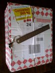
Therefore, I went to collect the parcel today, rather than wait for PF to recover it from the PO and redeliver. Certainly far larger than would have gone through my letterbox (that's a 15 cm ruler) and a signature was required. In fact the dent/hole in the side of the box was far larger than the (unpacked) contents. Somehow the large yellow "Convenient Delivery" sticker doesn't seem entirely appropriate. :(

RSbox.jpg

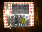
Fortunately, the components were in electrostatic bags, each within a separate fancy pink paper bag, together with several sheets of paper and the ubiquitous "air bags", so nothing was lost. My second photo shows the actual components, with the sensor in the centre.

RSboxContents.jpg

* Generally I'm quite a fan of our Royal Mail. Most of my projects rely on a few of their elastic bands (you probably need to live in a UK town to appreciate the joke).

Cheers, Alan.
 
Last edited:
Top