WhiteSpace
Well-known member
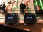
Using two SSD1306 OLED displays is obviously entirely gratuitous, but just in case anyone else wants to do so, here are some suggestions, which I hope will save some time. At the moment it's just a proof of concept.
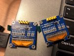
The first step is to be able to change the i2c address of one of the displays. I don't know if there's a software method - the only method that I'm aware of (there's quite a lot of stuff on discussion boards for [cough] other microcontrollers) is to re-position one of the resistors on the back. Not all displays have the ability - I discovered that I have some with and some without. I found a pack of 4 displays online that showed a picture of the back. You can see the spot to look for at the top left of the two displays below, helpfully labelled "iic address select". The left hand display has the resistor in its default position, soldered across the two left hand contacts. On the right hand display, I de-soldered the resistor and soldered it across the right hand contacts. I've never soldered tiny surface mount components before - it was very fiddly but I got it done after a couple of tries, without burning the display.
Once that's done, connect the two displays to the Picaxe.
The displays are then addressed, corresponding to the addresses shown on the back of the displays:
The same Symbols can then be used for both displays. Each display will need its own setup instructions. Then the key thing to remember is that each time you want to start a set of instructions to a different display, you need to address it:
Subroutines can be specific to one or other display, or common to both, so in the example above the subroutines that hold the instructions for "Hello" and "World" are specific to left and right displays, but the subroutine that converts the characters into dots on the screens are common to both.
I attach the file - I hope it's useful as a starting point.
The first step is to be able to change the i2c address of one of the displays. I don't know if there's a software method - the only method that I'm aware of (there's quite a lot of stuff on discussion boards for [cough] other microcontrollers) is to re-position one of the resistors on the back. Not all displays have the ability - I discovered that I have some with and some without. I found a pack of 4 displays online that showed a picture of the back. You can see the spot to look for at the top left of the two displays below, helpfully labelled "iic address select". The left hand display has the resistor in its default position, soldered across the two left hand contacts. On the right hand display, I de-soldered the resistor and soldered it across the right hand contacts. I've never soldered tiny surface mount components before - it was very fiddly but I got it done after a couple of tries, without burning the display.
Once that's done, connect the two displays to the Picaxe.
The displays are then addressed, corresponding to the addresses shown on the back of the displays:
Rich (BB code):
'I2C addresses
Symbol LeftDisplay = $78
Symbol RightDisplay = $7A
Rich (BB code):
hi2cout [LeftDisplay], (0)
gosub ClearDisplay

hi2cout [RightDisplay], (0)
gosub ClearDisplayI attach the file - I hope it's useful as a starting point.
Attachments
-
8.4 KB Views: 17
