'------------------------------------------------------------------------------'
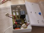
'TELEPHONE RELAY REMOTE CONTROL USING 20M AND DTMF DECODER
'AFTER THE CORRECT NUMBER OF RINGS ARE RECEIVED, THE PHONE IS 'ANSWERED'.
'PRESSING CORRECT 4 DIGIT DTMF CODE PASSWORD RESULTS IN VERIFICATION TONE
'SUBSEQUENT OUTPUT 'SWITCHING OF TWO INDEPENDENT RELAYS VIA CORRECT DTMF TONES WITH VERIFICATION 'SOUND DETERMINING RELAY STATE AS WELL AS 'HANGING 'UP' BY USING APPROPRIATE 'DTMF TONE
'I/P4 CONNECTS TO PIN 'DV' ON THE DECODER CHIP FOR DTMFin
'I/P5 CONNECTS TO 'RING DETECTION' CIRCUIT
'O/P6 CONNECTS TO 'ANSWER' RELAY
'O/P0 IS VERIFICATION 'SOUND OUT'
'O/P1 DRIVES A RELAY AND ALSO CONNECTS TO I/P7 FOR STATUS MONITORING
'O/P2 DRIVES A RELAY AND ALSO CONNECTS TO I/P6 FOR STATUS MONITORING
'O/P7CONNECTS TO 'OE' PIN ON DTMF CHIP TO INITIALISE CODE OUTPUT
'Password and all DTMF tones are selected/changed by selecting appropriate EEPROM address
'and downloading 'updated' code into picaxe
'------------------------------------------------------------------------------'
symbol ring_count=w5
symbol timer=w6
symbol ring=pin5
symbol DTMFin=pin4
symbol code_1=b5
symbol code_2=b6
symbol code_3=b7
symbol code_4=b8
'------------------------------------------------------------------------------'
'eeprom values contain the BCD value of the decoded DTMF tones from 0 to 9
'------------------------------------------------------------------------------'
eeprom 0,(%1010) 'loads DTMF character0 into eeprom
eeprom 1,(%0001) 'loads DTMF character1 into eeprom
eeprom 2,(%0010) 'loads DTMF character2 into eeprom
eeprom 3,(%0011) 'loads DTMF character3 into eeprom
eeprom 4,(%0100) 'loads DTMF character4 into eeprom
eeprom 5,(%0101) 'loads DTMF character5 into eeprom
eeprom 6,(%0110) 'loads DTMF character6 into eeprom
eeprom 7,(%0111) 'loads DTMF character7 into eeprom
eeprom 8,(%1000) 'loads DTMF character8 into eeprom
eeprom 9,(%1001) 'loads DTMF character9 into eeprom
initialise:
setfreq m8
start:
low 6 'turns off 'answer' relay
ring_count=0 'resets b9 to 0 before starting again
main:
if ring=0 then main 'loop if no incoming call,if call detected then
'gosub 'ringing'
ringing:
if ring=1 then ringing 'waits for normal pause in ringing tone
inc ring_count 'increment ring_count by 1 on each loop
if ring_count=250 then answer 'allows the call to be answered after 300 ring pulses
timer=0
do
inc timer 'increments timer by 1 on each loop
if ring=1 then ringing 'if ringing restarts then go back to the 'ringing' routine
pause 1 'value sets delay
if timer=6000 then start 'returns to beginning after 3secs (8Mhz) timeout
'(suggests caller hung up)
loop
answer:
high 6 'energise relay to 'answer call'
pause 1500 'wait 750mS (8Mhz) for line to settle
sound 0,(90,50,0,20,90,50,0,20,90,50) 'gives triple tone for successful 'pick-up'
gosub wait_for_DTMF 'goes to routine and waits for DTMF tone
let b1=b0 'read first decoded tone and store in b1,
gosub wait_for_DTMF 'goes to routine and waits for DTMF tone
let b2=b0 'read first decoded tone and store in b2,
gosub wait_for_DTMF 'goes to routine and waits for DTMF tone
let b3=b0 'read first decoded tone and store in b3,
gosub wait_for_DTMF 'goes to routine and waits for DTMF tone
let b4=b0 'read first decoded tone and store in b4,
read X,code_1 'loads eeprom into variable b5 for code set
read X,code_2 'loads eeprom into variable b6 for code set
read X,code_3 'loads eeprom into variable b7 for code set
read X,code_4 'loads eeprom into variable b8 for code set
if b1<>code_1 or b2<>code_2 or b3<>code_3 or b4<>code_4 then
goto fail_tone 'compares security code and continues if correct
end if
gosub pass_tone 'gives tone for successful security code
read X,code_1 'loads eeprom into variable b5
read X,code_2 'loads eeprom into variable b6
read X,code_3 'loads eeprom into variable b7
switch_relay:
low 0 'ensures 'sound' output is off
let timer=0 'resets timer counter to 0
do
gosub wait_for_DTMF 'goes to routine and waits for DTMF tone
if b0=code_1 then toggle_down 'toggles downstairs heating on receipt of correct DTMF tone
if b0=code_2 then toggle_up 'toggles upstairs heating on receipt of correct DTMF tone
if b0=code_3 then fail_tone
loop
toggle_down:
toggle 2 'toggle pin 1 (downstairs heating)
pause 20 '10mS delay (8Mhz) to allow output to toggle
if pin6=1 then 'check state of output1 (i.e.is it on or off)
sound 0,(90,100) 'create tone for output1 on
else
sound 0,(30,100) 'create tone for output1 off
end if
goto switch_relay
toggle_up:
toggle 1 'toggle pin 2 (upstairs heating)
pause 20 '10mS delay (8Mhz) to allow output to toggle
if pin7=1 then 'check state of output2 (i.e.is it on or off)
sound 0,(90,100) 'create tone for output2 on
else
sound 0,(30,100) 'create tone for output2 off
end if
goto switch_relay
pass_tone:
sound 0,(90,75,100,75) 'create tone for successful operation
low 0 'ensures O/P3 is turned off after tone
return
fail_tone:
sound 0,(30,250) 'create tone for un-successful operation
low 0 'ensures O/P3 is turned off after tone
goto start
wait_for_DTMF:
let timer=0 'resets timer counter to 0
do
if timer=5000 then fail_tone 'jumps to 'fail_tone' when timer times out
pause 2 '1mS pause (8Mhz) for 'timeout' timer
let timer=timer+1 'increments timer by 1 for the 'timeout'
if DTMFin=0 then loop 'loops until next DTMF signal is recieved and 'DV' pin goes high
end if
do
if DTMFin=1 then loop 'loops until DTMF 'DV' pin goes low and O/P code has latched
end if
high 7 'turn on DTMF code o/p pins
pause 10 'slight delay to allow DTMF outout to settle
let b0=pins & %0001111 'read first decoded tone and store in b0, masks high nibble
pause 10 'slight delay before turning off DTMF chip pin O/P
low 7 'turn off DTMF code o/p pins
pause 400 '200mS (8Mhz) delay before allowing new DTMF tone to be recognised
return
 191.6 KB Views: 351
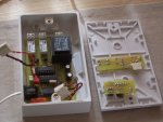 184.3 KB Views: 284