Driving LED bar graphs

Sodapep

Member
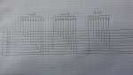
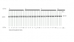
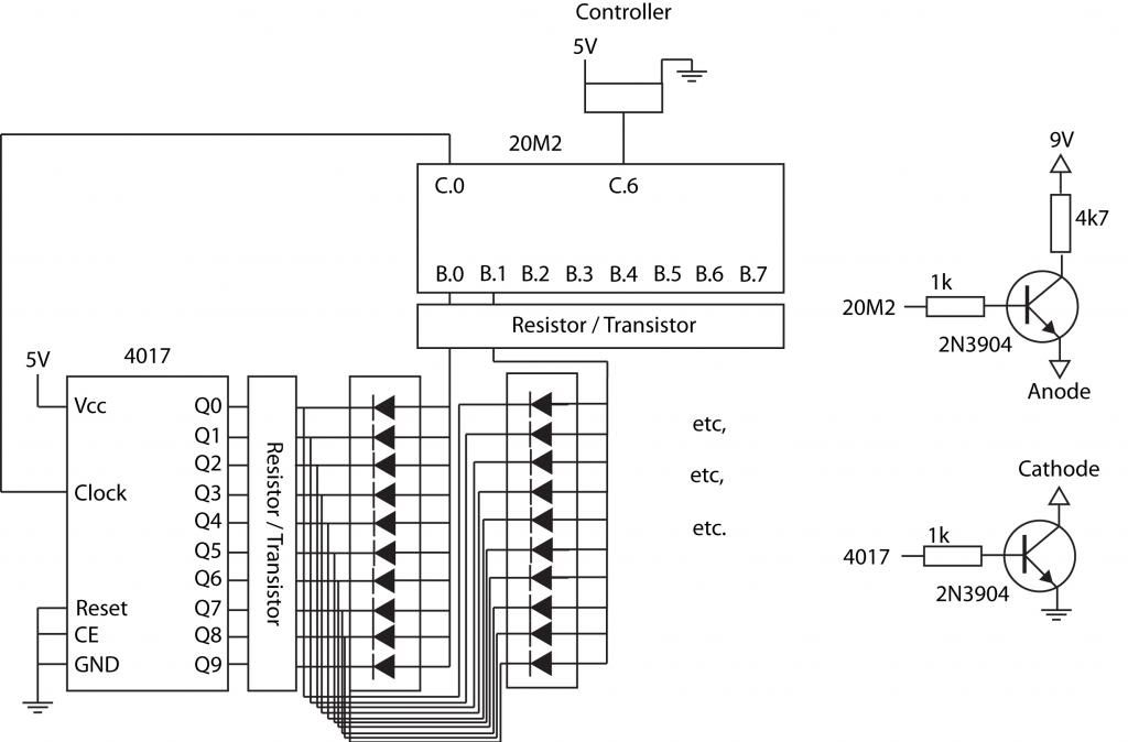
As my second PICAXE project, I'd like to work with LED bar graphs, such as these:


Possibly using LM3914 bar graph driver trips:

http://www.ti.com/lit/ds/symlink/lm3914.pdf

The idea is to use eight 10 LED bar graphs linearly lined up to show the position of a 10k potentiometer. Before I start reading up about the basic ideas and code used for this kind of thing, I'm having trouble understanding how linking the LM3914's work. I can grasp the idea of using one driver and a defined voltage ladder, but I'm not sure how they work when chained together (8 in series in my case).

I guess the initial question should be - can a PICAXE handle this kind of thing?

Thanks in advance for any tips on the chaining of IC's and further questions. I appreciate all of those who put time into helping others on this forum!
 

westaust55

Moderator
In the datasheet it explains how to cascade/daisy-chain multiple LM3914:
http://pdf1.alldatasheet.com/datasheet-pdf/view/8900/NSC/LM3914N-1.html

Dot Display, 20 or More LEDs:
Connect pin 9 of the first driver in the series (i.e., the one with the lowest input voltage comparison points) to pin 1 of the next higher LM3914 driver.
Continue connecting pin 9 of lower input drivers to pin 1 of higher input drivers for 30, 40, or more LED displays. The last LM3914 driver in the chain
will have pin 9 wired to pin 11. All previous drivers should have a 20k resistor in parallel with LED No. 9 (pin 11 to VLED)
From page 7 onwards there is description and diagram showing the cascading method.
Note that a PICAXE can only output a voltage via its DAC pin nominally up to the PICAXE supply voltage.

For any reasonable resolution making use of 80 LEDs you will need an extrenal DAC or digital pot to have 128 or 256 steps. (64 step devices would not give adequate resolution skipping some LEDs).

EDIT:
If you look in the internal schematic in the datasheet, you will find a resistor divider ladder comprising 10 x 1 kOhm resistors between Rlo and Rhi, with comparators on each tap.
To cascade multiples of these ICs you need to connect these ladders in series to form a bigger 80 resistor ladder, and connect the signal voltage to all 8 inputs.
Connect upper voltage reference to Rhi of the first IC, Rlo of the first to Rhi of the second, Rlo of the second to Rhi of the third and Rlo of the third to the lower voltage reference.
Tie to top Rhi to 5V and the lowest Rlo to ground and forget the internal 1.25 voltage reference. Then you should (untested) have a linear scale of 8 LED from 0 to 5V.
 
Last edited:

PaulRB

Senior Member
Hi Sodapep,

You say this is a picaxe project, but I don't see why you need a picaxe for what you describe. Those driver chips do it all for you (but you will need 8 of them).

If 6 bar graphs is enough, you could use an 08m2 to do the ADC and also drive a single MAX7219 to drive all 60 leds. A second MAX7219 could drive another 60 leds if needed.

Paul
 

AndyGadget

Senior Member
For any reasonable resolution making use of 80 LEDs you will need an extrenal DAC or digital pot to have 128 or 256 steps. (64 step devices would not give adequate resolution skipping some LEDs).
Is there any reason he couldn't use READADC10 with PWMOUT and a small resistor / capacitor network on the output to give 1024 steps of resolution?
I don't know how linear this would be so may need a bit of code to straighten it out.
 
Last edited:

nick12ab

Senior Member
Using this amount of LM3914s would be very costly. There is no reason why the bargraph display cannot be driven directly from the PICAXE using multiplexing and/or shift registers.
 

PaulRB

Senior Member
The OP only needs 7 bit resolution for 80 leds, so readadc10 not needed.

But all the picaxe and a R-C network would be doing is turning an analog signal into a digital and back to analog again. What's the point of that!?! Why not just feed the pot output straight to the barcode driver chips and ditch the picaxe? Hence my max7219 suggestion above...
 

techElder

Well-known member
In the interest of explosive mission creep (which inevitably happens here on occasion), what's the fun in a bar graph? Rig your hardware design so that each LED in the bar is addressable!

Now you can make any kind of graph you want! Even random! <GRIN>
 

AndyGadget

Senior Member
The OP only needs 7 bit resolution for 80 leds, so readadc10 not needed.
I was considering the 'graininess' of the control. 1024 steps would make for smoother transitions when turning the pot.
Agreed about the whole concept though. More sense to stay digital.

Sodapep, what's the eventual use for this? A serious project or just because you want to.
(Absolutely nothing wrong with that - I do it all the time.)
 

Buzby

Senior Member
Using this amount of LM3914s would be very costly. There is no reason why the bargraph display cannot be driven directly from the PICAXE using multiplexing and/or shift registers.
Fully agree !.

PICAXE can more cost effectively drive the LEDs using multiplexing.
An 80 LED display maps nicely to a 10 x 8 multiplexed matrix.

A 28 pin PICAXE could easily handle this, and is a lot less expensive than eight LM3914s.
 

Steve2381

Senior Member
I like max7219 chips... but they are mentally expensive (around £10 now- unless you stab at some dodgy Ebay ones). Same goes for a pile of LM3914's
Yep - I agree with Buzby, I would try multiplexing off a 28 pin Picaxe
 

Sodapep

Member
Wow thanks for all the replies!

AndyGadget - I apologize for being vague in my OP. The purpose of this is to be a visual indicator for the location of the potentiometer. The 'pot' in this case is actually a long strip of carbon with a strip of material floating on top coated with metal (silver I think). The whole strip is 200mm. A finger or other actuator is used to depress somewhere along the strip causing contact between the two layers completing the circuit somewhere between 100R and 10K ohms. Looks like this:


The 'pot' is controlling an oscillator. The bar graph would span the potentiometer range and show realtime where the potentiometer is being pushed, as well as continue to be lit even when the potentiometer is not being pushed (so user can see where it was last pushed). There are actually more LED's in 8 bar units, but 7 would be too little. I'm sure that is going to cause some problems at some point.

westaust55 - Thanks for the explanation. I saw on the datasheet how to hook them up, but I wasn't sure what the operating parameters were. Makes sense now though, just expand the voltage swing into smaller units for each LED.

All you other fine forumites - Thanks for the ideas! Good call on the PICAXE + LM3914 being overkill. While the MAX7219 seems like a cool idea, I think I'll look into the multiplexed matrix. To Google!

Thanks everyone.
 

Sodapep

Member
Yep! I had saw Sparkfun has them, but I got one a while back in a grab bag from a site I can't remember... electronics goldmine maybe. In any case, I'm thinking something along the lines of a tannerin, like this:

http://www.youtube.com/watch?v=bhlQ27fbQ30

but instead of the mechanical slide bit, using a softpot. Instead of all-in-one unit like the tannerin, I'd use it as more of a control into various synth stuff I have laying around.

Another thought came about - similar concept - but defining certain ranges of voltage when the oscillator is set to a certain speed, translating those voltages into frequencies in a scale and have that displayed overtop of the location bar graph. I'd imagine the framework wouldn't be too far removed from the 10x8 matrix. It would be similar to the picture of the piano on the tannerin video above but definable based on a few set oscillator selections. Thoughts, anyway, first to get the position bar graph to work!

Also, found a thread by westaust55 about shift registers and it seems a lot of people who make matrices with arduino's use shift registers and decade counters together to make things work. Could be a viable route!
 
Last edited:

westaust55

Moderator
I presumed that you might have had the LM3914 chips already.

Many shift registers chips typically only provide 8 outputs each (I think there is a 16 output version of the 74HC595 but do not recall the part number) so you would need jsut as many chips as the LM3914.
LM3914 is $1.75ea at Futurlec (www.futurlec.com.au or futurlec.com) whereas 74HC595 is $0.50ea so there is a cost saving but not PCB area saving as you may need 10 shift register chips for 80 LEDs.
Multiplexing can reduce the chips count.

I have also used MCP23017 chips which are i2c comms based IO expanders providing 16 bidirectional IO in a single chip (used two in a past project posted here to drive an 8x8 RGB matrix (that is in effect 192 LEDs) which need only two PICAXE pins.

Whether using i2c or shift registers there will be a slower update than using a suitably sized PICAXE chip and directly driving the LED matrix via the PICAXE pins - but keep in mind the 20 mA max limit and a total chip current of around 100 mA in some cases so added transistors may be necessary.
 

nick12ab

Senior Member
That is multiplexed. The MAX7219 is for common cathode displays so this wouldn't work with one (actually it might do if you are willing to have a weird addressing system), but since a PICAXE can do the multiplexing a costly MAX7219 is not required. There are also only 64 LEDs, not the 80 that the OP is using.
 

PaulRB

Senior Member
That is multiplexed.
Yes, the OP is considering multiplexing. This module might save some tricky breadboard wiring.
The MAX7219 is for common cathode displays so this wouldn't work with one
The OP has already discounted max7219.
There are also only 64 LEDs, not the 80 that the OP is using.
We don't know if the OP has purchased any displays yet, or if the number 80 is critical.

Paul
 

Sodapep

Member
PaulRB - Nice find! The actual number of LED's isn't critical, it's the length that the LED's would span that is most critical. The unit I was looking at was 25.5mm long with 10 LED's, making a 8 units needed to span the entire 200mm of the softpot, with a few LED's to spare. The unit you linked to is 100mm long, so two of them would actually be pretty good, however that bumps up the LED count from 80 to 128. Would increasing the number of LED's to 128 cause a lot more difficulty? The 80 seems to work out pretty well (see below) with a 4017 and PICAXE; I'm not sure if 128 would be only a bit harder or cause much more problems.

I'm still attempting to grasp how this is going to work with 80, so I came up with the following diagram:


So the picaxe would read the voltage on the controller, send a clock signal to the 4017 to connected the appropriate LED to ground and then set one of the pins high to connect the LED to 9V. Is that the basic idea of how this is supposed to work? Does anyone recommend any commands to study?
 

westaust55

Moderator
That 4k7 Ohm resistor in series with the two transistors and LED will severely limit the current through the LEDs.
From the 2N3904 datasheet, if you drive the two transistors into saturation VCE will by interpolation be around 0.25 volts at 20 mA.
So the LED with a forward voltdrop of 2.0V (see the link PaulRB gave) results in 2.5 V across transistor/LED combination.
From your 9V supply that leaves 9 - 2.5 = 6.5 Volts. Current will therefore be V / R = 6.5 / 4700 = 0.00138 A or 1.4 mA. You would likely want at least 10 to 12 mA for continuous power and for PWM or multiplexed operation maybe30 mA or even 50 mA.
For say 30 mA the resistance needs to be V/I = 6.5 / 0.030 = 216 Ohms.

Now for the transistor base resistors:
from analysis of the datasheet HFE(sat) = 10 (ie Ic = 50mA and Ib = 5 mA)

For the low side cathode switch at Ic =30 mA ==> R = V / I = (5 - 0.9) / 0.030 Amps = 136 Ohms = use say 120 Ohms to ensure transistor saturation

For the high side anode switch at Ic =30 mA keep in mind the emitter is at 2.25 V so R = V/ I = (5 - (2.5+0.9)) / 0.030 Amps = 53 Ohms use say 51 Ohms.
 

PaulRB

Senior Member
Hi Sodapep, some more suggestions for you:

UDN2981 is an 8 channel high-side driver that might replace your cathode transistors.
ULN2803 could replace the anode transistors. Unfortunately you need 10 and it has only 8.
You would still need the current limiting resistors.

Also, if the length is more important than the number of leds, how about these?

http://www.ebay.co.uk/itm/Kingbright-5-segment-White-LED-Bargraph-Array-Green-/300691611891?pt=UK_BOI_Electrical_Components_Supplies_ET&hash=item46029de0f3

You would only need 7 to make a display around 200mm, so only 35 leds.


Paul
 
Last edited:

BeanieBots

Moderator
There are many digital methods that will work and I'll leave to other to make their suggestions (I'd go with MAX7219), however, the LM3914 method will NOT work.
It's resolution is too low. The maximum number of LEDs you can control using LM3914s is only about 30. Anything above that will result in flickering and/or multiple LEDs on when using it in dot mode.
 

PaulRB

Senior Member
Sodapep, Beaniebots' mention of "dot mode" gave me an idea. 10 input/output lines, 10 resistors, no multiplexing, no driver chips or transistors. Someone had to say it so it might as well be me: Charlieplexing!

Only if you are ok with dot mode though. Bar mode not impossible with charlieplexing, but display might be rather dim due to multiplexing and pic maximum currents. A few transistors help somewhat with that.
 

nick12ab

Senior Member
An NPN transistor is not suitable as a high side switch. A PNP transistor should be used instead, with an NPN transistor on the base because the PNP transistor will be on at all times when connected directly to the PICAXE (through a resistor) because of the higher voltage used for the LED power supply which isn't necessary anyway - use a switching regulator to provide the 5V then you can use that supply for the LEDs without the regulator getting hot.
 

Sodapep

Member
westaust55 - Thanks for the math (again!). I thought I may have understood it the first time when you got me in my button pushing problems hah. Also, congrats on 10k posts!

BeanieBots - Thanks for the input. The LM3914 will be discounted.

PaulRB - I had a look at the UDN2981 and it's not available from any of my normal suppliers. I also have a boat load of transistors in my drawers to use. Dot mode is the objective of this project, which I didn't even think about bar mode - but that would be a lot of LED's to light and I'd rather dot mode anyway. Charlieplexing looks interesting... would it work fast enough to light LED's as the potentiometer is slid around on? Also seems like it would be strange code?

nick12ab - I had a 9V source in the project and used it because I was thinking lighting LED's with the same regulator that is powering the PICAXE might be too taxing. Are you saying that if I power the LED's with another 5V source, I would be able to use the NPN setup I have, or would I still need to use the PNP/NPN setup you mentioned? Also, as far as the setup of what you are talking about, is it this but rather than the load going to ground, it would be the cathode NPN transistor controlled by the 4017?


Also, to anyone - what is the reason to using a 28M2 over a 20M2? They both seem to have enough i/o configurations.
 

PaulRB

Senior Member
Charlieplexing looks interesting... would it work fast enough to light LED's as the potentiometer is slid around on? Also seems like it would be strange code?
It would be less code and faster than other types of multiplexing. But are you sure about dot mode? = 1 led only lit at any time? If so, charlieplexing is a no-brainer IMHO.

As I said earlier, for 80 leds, you would need 10 picaxe pins, each capable of being an input or an output. With N pins, you can charlieplex up to N x (N - 1) leds, so 10 lines would be good for up to 90 leds. 9 lines would only go up to 72 leds.

This means a 14m2 is just too small (14m2 would be fine for up to 56 leds), so a 20m2 will be OK.

Group your 80 leds into adjacent groups of 9. The last group will only have 8. Common-up the cathodes within each group. Then within each group, one line goes to the common cathodes, and the other 9 lines go to each of the anodes. So in the first group, line 1 goes to the cathodes and lines 2 to 10 go to the anodes. In group 2, line 2 goes to the common cathodes and lines 1 and 3 to 10 go to the anodes. In group 7, line 7 goes to the common cathode and lines 1 to 6 and 8 to 10 go to the anodes. And so on...

Then you just need a current-limiting resistor for each line, which would be half the R value that you would normally calculate, because the current will always pass through 2 of the resistors.

Code-wise, you would set all 10 lines to input (=high-impedance), and then set one line to output high and one line to output low to cause a single led to light.
 
Last edited:

nick12ab

Senior Member
nick12ab - I had a 9V source in the project and used it because I was thinking lighting LED's with the same regulator that is powering the PICAXE might be too taxing. Are you saying that if I power the LED's with another 5V source, I would be able to use the NPN setup I have, or would I still need to use the PNP/NPN setup you mentioned?
If using the same supply voltage for the PICAXE, you still need to use the PNP transistors on the anode side, but you no longer need the NPN transistors on the bases. If you only use NPN transistors on the positive side then it might work but it won't work very well - probably less well than a PNP transistor inserted the wrong way!

Also you don't need to have a separate 5V supply for the LEDs, and if you will only have one dot on at a time then using the existing linear regulator will be OK as well. If you decide you want to have many dots on at once then consider using a switching regulator as a linear regulator will be inefficient and get hot.

Also, as far as the setup of what you are talking about, is it this but rather than the load going to ground, it would be the cathode NPN transistor controlled by the 4017?
Sorry, I don't understand what you mean by that.
 

PaulRB

Senior Member
Also, to anyone - what is the reason to using a 28M2 over a 20M2? They both seem to have enough i/o configurations.
The 28x2 would have:
1. enough pins to do the multiplexing without other decoder chips like 4017
2. faster speed to multiplex with less flickering (not sure this would be needed)
3. more current source/sink capacity - 200mA I seem to remember, vs. 100mA for 20m2, which might be enough to drive more leds reasonably brightly, without transistors

But... if you only need dot mode, its all academic - see my earlier post!

Paul
 

Buzby

Senior Member
Hi Sodapep,

I've just reprogrammed my orrery to test the 80 LED idea.
Here are 80 LEDs Charliplexed off a 40X2, but a 28 pin would do just as good. http://youtu.be/XS3jYw8U_Ws

Flicker starts to set in when about 30 LEDs are lit, and it's very noticeable at 80, so I don't think Charliplexing is the answer.
My code is a bit rough, it could be speeded up for specific patterns, like the bar graph, but I don't think it would ever be flicker free at 80.

However, it's perfect for a moving dot, or a short bar.

Because it is Charliplexed it uses no active driver components, just the PICAXE and some resistors.
You can use the same 'no driver' idea with multiplexing, but the currents go up.

A multiplexed 8x10 matrix will not have flicker, so that's your best idea for a full bar graph.
Using high-brightness LEDs you can run at less than 5mA each, which is what the orrery does.

Multiplexing at 8x10 would need 40mA per column, which is too much for a PICAXE output pin to handle.
But a 4x20 matrix would only need 20mA per column, so could be safely driven directly from a PICAXE.

Food for thought ?

Cheers,

Buzby
 

PaulRB

Senior Member
... so I don't think Charliplexing is the answer...
However, it's perfect for a moving dot, or a short bar.
Yes, as I said before, it all comes down to the bar vs dot question, but I the OP has said that a dot is the requirement, although I'm still a little concerned we mean the same thing by that.

Buzby, with your > 30 leds lit at once, what would the multiplex ratio have been? With the circut I described above, I would modify it slightly if a bar needed to be lit. I would common the anodes rather than the cathodes and have a driver npn for each of the 9 anode groups. This would allow a current of around 10mA per led and a multiplex ratio of 1:9, hence my concern over brightness. The average current would only be around 1~2mA for each led.

But if only a single dot is lit, no transistors needed for a current of 20mA and no multiplexing, so nice and bright.
 

westaust55

Moderator
westaust55 - Thanks for the math (again!). I thought I may have understood it the first time when you got me in my button pushing problems hah. Also, congrats on 10k posts!


The above 2-transistor will definitely work. You may need to reduce the value of R3 if you need higher current into the LEDs which is typical when using multiplexing or PWM methods.

Contrary to some suggestions there are times when an NPN transistor will function as a high side switch as in your case/earlier schematic. (see the calcs I provided at post 19)
If the PICAXE driving the transistor base to almost 5 volts is high enough to raise the base at least 0.7 Volts above the emitter then the transistor will turn on and the load/LED work.

So with a PICAXE at 5 Volts as long as the load does not need a voltage greater than say 4.3 volts (say 4 volt to be safe) all would be well.
The LED and a low side transistor in saturation is in effect a forward volt drop of 2.3 to around 3.5 volts depending on transistor and LED colour which is less than the 4 volts so it would work.

Keep in mind that if the load were to need a higher voltage however that such a scheme/circuit will most likely not work.

In summary a PNP transistor is NOT always mandatory for a high side switch but there are times when voltage levels dictate a PNP must be used. If unsure then a PNP can be the safe way.
 
Last edited:

Sodapep

Member
Buzby - thanks for testing it out! Looks really great. I see what you are talking about with the flickering. I don't intend of having that many LED's illuminated at once. Perhaps as some sort of start up sequence I'll flash some around for looks, but it's good to know that 30 is the limit before flickering. I'm thinking only having one or two LEDs lighting up at a time will be good enough show the position on the soft pot.

westaust55 - thanks for the explanation, very sensible.

So into the charlieplexing we go! I've done up a schematic for the full 90 LEDs/10 pins. I will only be using 80 of those, so the last 10 LED's are unnecessary, but I thought I'd cover all my bases. Time to figure out the code :confused: Is it as simple as scaling the 5v input in to 80 different measurements then jumping to whatever subroutine that measurement designates? Each subroutine would have the code to turn the necessary pins high, low or input. Seems lengthy.

Another problem I see could be the 100k soft pot. I've been reading that the analog inputs like to see 10k. Anyway around that?


Buzby

Senior Member
Hi Sodapep,

That's a cool circuit diagram !.

I didn't have a circuit diagram for my 528 Charlieplexed LEDs. I cheated and wrote a VB prog to 'draw' the PCB directly !.

In your case the PCB is much easier to layout.

Take a look at my first attempt, where I used 2 ten LED strips : http://www.picaxeforum.co.uk/attachment.php?attachmentid=7055&d=1295190229

And : http://www.picaxeforum.co.uk/showthread.php?17349-OT-Charlieplexing-my-head-hurts-!&p=157744&viewfull=1#post157744

You can just see the pattern of wiring the the photo.
It would have been much clearer if I had used 5 different colour wires !.

I see you have 75 ohm resistors.
I used 8-way resistor 'IC's in sockets. This let me quickly change the resistor values to find the best.

Regarding the Charlieplexing code, I can help you there.
My code is too complex for a simple job like yours, but the basic idea is easy enough to follow.

When you have the hardware built I'll give you a hand with the code.

Cheers,

Buzby
 

PaulRB

Senior Member
Time to figure out the code :confused: Is it as simple as scaling the 5v input in to 80 different measurements then jumping to whatever subroutine that measurement designates? Each subroutine would have the code to turn the necessary pins high, low or input. Seems lengthy.
No, much easier than that, as long as you organise your leds into groups of 9 I mentioned earlier. Your schematic above shows you have the basic idea of charlieplex wiring right, but your leds are not in a straight line or organised into groups with common cathodes.

Once you have your 0..79 figure, divide by 9 to work out which group of leds to light ("X"), then use the remainder to work out which of the 9 in the group ("Y"). We can't have X=Y, so if Y >= X, increment Y. Then set line X high and line Y low. May have to use CASE commands for that last bit.

Paul
 
Last edited:

PaulRB

Senior Member
Another problem I see could be the 100k soft pot. I've been reading that the analog inputs like to see 10k.
You may find that the least significant bits have some noise on them due to this. Take several readings and average them.
 

Buzby

Senior Member
No, much easier than that, ... your leds are not in a straight line
As Paul says, if you draw the LEDs in a straight line it will make understanding the problem much easier.

When you have this, label the LEDs 0 to 79.

You then need a table with 80 pairs of values, holding the relevant 'anode' and 'cathode' IO pin numbers for each LED.
I had my table in external I2C EEPROM, because internal memory was not big enough for 528 LEDS.
You only have 80 LEDs, so the table is going to be 160 bytes, which fits easily into any PICAXE. ( See the 'EEPROM' instruction in Manual 2 )

Then your code just needs to work out which LEDs need lighting, and call a subroutine for each.

Code:
' Main loop
do
        '
	' Calculate the numbers of the LEDs that needs lighting
	'

        '
        ' For each LED that needs lighting  
        ' Gosub ShowLED
        '
        '
loop


' Subroutine
ShowLED:

        EEaddress = LEDnum * 2                      ' Make pointer into table 

        Read EEadress , LEDanode, LEDcathode  ' Get the anode and cathode numbers for the LED

	High LEDanode	' Turn on the selected LED
	Low  LEDcathode
	
	Pauseus DisplayDuration		' Wait a short time

	Input LEDanode	' Turn off the selected LED
	Input LEDcathode	
	
Return
 

techElder

Well-known member
You guys are great at explaining charlieplexing! I think I'm finally beginning to understand it. Thanks!

PaulRB, can you explain further your comment?

... your leds are not in a straight line or organised into groups with common cathodes....
 

DakLak

New Member
Interface with a MAX7219 LED Bar Graph

The MAX7219 is compact, serial input/output common-cathode display drivers that interface, with only 3 wires, PICs to 7-segment numeric LED displays of up to 8 digits, bar-graph displays, or 64 individual LEDs.

Here is an example to drive 4 7-segment with a 08M. (Author unknown - collected by a bot)


Code:
'     +V 1 U 8 0V
'          2   7 to 7219 DIN  = DATA IN 
'          3   6 to 7219 LOAD
'          4   5 to 7219 CLK

  symbol DIN  = 0
  symbol LOAD = 1
  symbol CLK  = 2
  symbol LEN  = 1    'pulse duration

  low DIN
  low LOAD
  low CLK
  
'init7219 
  b1=$09  'decode mode
  b0=$ff  '=yes, all digits=BCD
  gosub shiftout

  b1=$0a  'intensity
  b0=$0f  '=max
  gosub shiftout

  b1=$0b  'scan limit
  b0=$03  '=4 digits, $00=1 digit only, $01=2 digits only, ...
  gosub shiftout

  b1=$0c  'shutdown mode
  b0=$01  '=normal
  gosub shiftout

  b1=$0f  'display test
  b0=$01  '=all on
  gosub shiftout

  b1=$0f  'display test
  b0=$00  '=normal
  gosub shiftout

  b1=$0a  'intensity
  b0=$05  '=mid-low, $00=min on, $0f=max on
  gosub shiftout

main:
'  b1=digit position (1 to 8)
'  b0=value to display
'  gosub shiftout

'  to set the decimal point ON:
'  b0=value or $80
goto main 

shiftout:
  for b5=1 to 16
    w6=w0 & $8000
    low DIN
    if w6=0 then bit_is_low
    high DIN  
bit_is_low:
    pulsout CLK,LEN
    w0=w0*2  '<< (shift bits left) 
  next b5
  pulsout LOAD,LEN
  return
 
Last edited by a moderator:
Top