driving a triac

ahellard

New Member
Can someone help me with some code to drive a 120v light bulb with a traic?

I have the circuit built i just dont really know how to write the code. Im using a 18x chip. I would hope i could use pin 18 for zereo crossing detection and pin 3 to use pwm to control the the light levels.

I want to be able to push a single input say pin 17 input(0) four times
1st push low
2nd push middle
3rd push high
4th push off

Any help would be greatly appreciated
AH
 

hippy

Ex-Staff (retired)
It's a form of PWM ( phase-angle control ) but not PWM in the sense of a free-running PWMOUT output, and you don't need PWM hardware to do it.

From zero-crossover, you have a time to the next zero-crossover and where within that period the triac is turned on determines the lamp's brightness every cycle.

Your basic program will be -

Wait for zero-crossover
Delay some time ( less delay = brighter lamp )
Turn triac drive off
Pause
Turn triac drive off
Repeat

Triacs latch once turned on so you only have to pulse its drive long enough to get it to latch, then it will stay on until the next zero cross-over when it unlatches. For 100% brightness you can keep the drive permanently high, for 0% permanently low.

I recall there was a previous project doing this so a forum search would be in order.

Take care with any mains controlled or connected project. Never work alone with mains. Ensure you use ELCD, RCD and/or other safety precautions.
 

kevrus

New Member
You could use a Opto Zero-Crossing Triac Isolator such as the MOC3041 to drive your triac...this will give you the zero-crossing switching without having to write code to detect it. more fun writing the code though
 

ahellard

New Member
still dont quite dont understand

18x picaxe
main:
if pin1 = 0 then 'zero crossing goes low at zero
pause 10 'pause
low 2 'turn triac off
high 2 'turn triac on
low 2 'turn triac off
pause 1 'pause
high 2 'turn triac on
low 2 'turn triac off
endif
goto main

the best i have accomplished is to make the light flicker
 

ahellard

New Member
I'm using a H1AA1 to detect zero crossing and a
MOC3041 to drive the triac.

Could this be the problem? I tried the without the H1AA1 but I thought that was my problem so i added it. It may have been my code
 

gengis

New Member
I don't know what an H1AA1 does best but the MOC3041 IS a zero crossing triac driver. It will only fire on the zero crossing no matter what you really want to do.

Your goal is to control light level if I'm reading this correctly. A ZC driver is not the way to go. You want phase control. The ZC driver can only fire at the ZC and in the US that means every 8 milliseconds it could fire.

There's a technique for adding an opto isolator to an ordinary lamp dimmer. This gives you a cheap and dirty way to employ phase control. The 'axe puts out a PWM signal that has to be integrated with a capacitor (charge pump style) to a DC level then it controls a mosfet output opto. Mosfet (or photo cell) because it needs to vary resistance linearly, and bi directionally, with voltage input. (photocell and 6 volt bulb in a light tight case and you can roll your own)

There's a lot of info on basic stamp lamp controls; The file you want is called "An AC lamp dimmer for the Basic Stamp" http://www.cs.cmu.edu/~RAS/Docs/space/dimmer.html
 

hippy

Ex-Staff (retired)
First check that the input goes active low when zero-crossing is detected, then I'd suggest optimising your code and reducing the initial pause time -

Do
Do : Loop Until pin1 = 0
Pause 2
High 2
Pause 1
Low 2
Loop

How long does the zero-crossover pulse last for and how does it synchronise to the AC ? There can be two issues here; too short and it may sometimes be missed, too long ( or with too short an initial pause ) and you may sometimes be firing the triac while on the going to zero-crossover of the AC.

A better solution to using "Do:Loop Until pin1=0" would be to use a PULSIN on pin 1. That should complete execution as the zero-crossover signal finishes with much greater consistency each time.

Ideally you need to look at what is happening on a scope, seeing how the zero-crossover relates to AC and how the triac firing pulse relate to that. Usual warnings about using scopes, 0V, 'ground' and earthing with mains present apply.

I'm not familiar with either H1AA1 ( don't even know what one is ) or MOC3041 but it would probably help if you posted your circuit. I don't understand how you mean you are using the MOC3041 to drive the triac - from the PICAXE ? That doesn't seem to be an appropriate way to drive a triac.

Also, what previous experience have you had with mains and lamp control ?
 
Last edited:

gengis

New Member
I'm not familiar with either H1AA1 ( don't even know what one is ) or MOC3041 but it would probably help if you posted your circuit. I don't understand how you mean you are using the MOC3041 to drive the triac - from the PICAXE ? That doesn't seem to be an appropriate way to drive a triac.
The MOC3041 is a zero crossing optical isolator intended to drive triacs directly. You can't use one to turn on the triac part way into a cycle, it will sit there and if power is still applied when the zero crossing rolls around, the triac will come on. A way to use one for dimming, might be to turn it on and let a predetermined number of cycles to flow - say with relatively slow PWM on the order of ~ 50 milliseconds - gate a few cycles of power through then turn it off for a period. With a power line frequency of 50 hertz, a zero crossing only comes up every 10 milliseconds - so expect aliasing and flicker unless everything is synchronized and even then there may be flicker.

We had an ancient electric rail system that used 30 hertz power to the rails - and all the lights in the station had noticeable flicker.
 

ahellard

New Member
Hippy, Thanks for looking at my code or the like there of. I'm new at the picaxe or microcontrollers for that matter. The H1AA1 is AC Input/Phototransistor Optocouplers it is designed to detect zero-crossing. I took a look at it on the scope it looks in sync with the AC wave form. I think the problem might be timming and the MOC3041. I believe MOC3041 is better suited to start and stop motors at the zero crossing. I have some new parts (triac drivers) on order.

I might have to call on You and Flooby again when i get my parts in.

What is a good program to be able to post my circuit diagrams to the forum?

I know you guys don't what to help people get hurt working with mains and i understand completely. I have a Masters and Contractors electrical license in the US.
Thanks again. This forum is great because of people like you helping people like me out.
 
Last edited:

ahellard

New Member
OK I got the new triac driver.

That doesnt seem to be the problem. I looked at the wave forms on the scope zero crossing looks good the problem seems to be that it is skipping about 10 cycles then works for 8 or so cycles.

Here is the code

pulsin 1,1,b1
do
b1 =0
high 3
Pause 6
high 2
Pause 1
low 2
Loop

Do you think the picaxe is too slow to be able to perform these instructsions?

i will try to load up these images off the scope today
 

kevrus

New Member
Sorry Ahellard, I think I may be missing something here, if you want the triac to switch at zero-crossing, then using the MOC3041 will acomplish that...when the LED in the optocoupler is switched on, the output will wait for the next zero-crossing before turning on...so why are you using the H1AA1?
I expect i'm a bit daft and missing something obvious
 

hippy

Ex-Staff (retired)
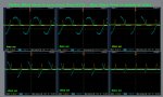
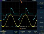
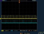
Although not entirely clear what represents what on te scope it looks like I'd expect given the code ...

Code:
pulsin 1,1,b1
do
  b1 =0
  high 3
  Pause 6
  high 2
  Pause 1
  low 2
Loop
Firstly, you only synchronise once, before the Do-LOOP so after that it becomes a free-running pulse generator. You need to synchronise to the zero-crossover for every half phase of mains.

Try a much simpler program to start with ignoring actual control of the triac / light ...

Code:
Do
  PulsIn 1, 1, b1
  PulsOut 2, 10
Loop
You should see a pulse on Pin 2 whenever the zero-crossover happens. If not then you have a hardware problem which needs fixing ( or PULSIN is looking for the wrong level ).

Then you can look at delaying the pulse until after zero-crossover. Use a PULSOUT to an otherwise unused pin and adjust the length of that pulse from 0 to ~8mS ...

Code:
Do
  PulsIn 1, 1, b1
  [b]PulsOut [i]?[/i], [i]?[/i][/b]
  PulsOut 2, 10
Loop
Choose a suitable PULSOUT time to put the triac firing pulse halfway through the phase, then alter the length of the time of the triac firing pulse to suit the triac, and with the light connected you should get 50% brightness.

Code:
Do
  PulsIn 1, 1, b1
  PulsOut [i]?[/i], [i]?[/i]
  PulsOut 2, [b]?[/b]
Loop
Now you can move the pulse along the phase angle, and determine what the minimum and maximum values of the time delay pulse can be ( w1 ) ...

Code:
Do
  [b]w1 = [i]?[/i][/b]
  PulsIn 1, 1, b1 
  PulsOut [i]?[/i], [b]w1[/b]
  PulsOut 2, [i]?[/i]
Loop
Then all you need to do is decide what 'w1' should be each time through the loop and you have your dimmer. Here's something which should give 0% to 100% dimming ...

Code:
Do 
  b1 = 50 ' 0 to 100 ( % brightness )
  If b1 = 0 Then
    Low 2
  Else
    If b1 >= 100 Then
      High 2
    Else
      w1 = 100 - b1 * [i]?[/i] / [i]?[/i] + [i]?[/i]
      PulsIn 1, 1, b1
      PulsOut [i]?[/i], w1
      PulsOut 2, [i]?[/i]
    End If
  End If
Loop
 

gengis

New Member
Sorry Ahellard, I think I may be missing something here, if you want the triac to switch at zero-crossing, then using the MOC3041 will acomplish that...when the LED in the optocoupler is switched on, the output will wait for the next zero-crossing before turning on...so why are you using the H1AA1?
I expect i'm a bit daft and missing something obvious
I'm lurking here too waiting for the lightbulb . . .

You can use one zero crossing device that tells the ax when the cross takes place and then use the axe for a delay to turn on the triac part way into a sine wave - via a NON ZERO CROSSING DRIVER FOR THE TRIAC.

What you can't do is use a ZC sensor for the axe and then tell another zero crossing driver (like you are doing) to turn on the triac at some time other than the ZC (what it sounds like you want-?)

Or I'm totally not understanding something here?
 

hippy

Ex-Staff (retired)
@ ahellard : With respect to kevrus's and Flooby's posts, and for the enlightenment of others who may have some advice to give, it really would help if you can describe what hardware you are currently using, particularly with respect to how you are getting your triac firing pulse to the triac.
 

ahellard

New Member
I tried your first code. You can see attachment Yellow(zero crossing)
Blue (pulsout)

Do
PulsIn 1, 1, b1
PulsOut 2, 5
Loop


I Replace the triac driver in a earlier post with a non zero crossing driver. I'm using a MOC3023M. I thougt that might have been the problem. which im sure it was part of the problem.

built the circuit with diptrace how do you upload the file?
 

Attachments

ahellard

New Member
Here is the circuit


kevrus, I replaced the MOC3041 with a MOC3023M it is nonzero-crossing

I use the H11A to determine when the zero crossing is because there would be no way to get it in sync with the picaxe pulsout command. (it would fire anywhere along the sine wave)

I really appreciate you all taking time to help me with this
 

Attachments

hippy

Ex-Staff (retired)
The scope trace looks promsing, so time to move on and see if you can get the firing to vary across the phase angle.

The circuit looks okay, I cannot comment on the mains interfacing side but the MOC3023M looks like it's the right thing to be using.

So it looks like everything should soon be working.
 

gengis

New Member
OK now I get it.

You know, there's a painfully simple way to do this. A incandescent lamp 6-12V pilot lamp in a tube with a photocell. Drive the lamp with the picaxe and PWM to vary the brightness then use the photocell's varying resistance to substitute one side of a ordinary triac lamp dimmer's potentiometer.

The lamp filament's time constant will ignore the PWM - it can only heat and cool but so fast, so will stay at a constant (variable) brightness. The whole thing could fit inside a standard lamp dimmer if that were desirable.

Beauty of it - the lamp filament automatically performs the integration function between PWM and a linear output, and the system provides electrical isolation. Lamp filament can be sized (under driven) to last forever.

Back in the old days (60's) guitar players used to insert the photocell in series with their volume controls to provide a vibrato by driving the lamp with a very low frequency sine wave. Lamp/Cell was made by a company called Vactrol - they are still available, but it is more fun and cheaper to roll your own. We used to do something similar in the 70's to make solid state relays - cheaply.
 

gengis

New Member
Come to think of it, it (vactrol idea) would probably work with a led as well - since photocells aren't exactly high speed devices, and the axe and leds can work in the >20KHZ range.
 

ahellard

New Member
Here is where I'm at this far. The code below is working

US power 60hz
16.6ms complete sine wave
8.33ms per half wave


No pause full on
1ms pause 88% on
2ms pause 76% on
3ms pause 64% on
4ms pause 52% on
5ms pause 39% on
6ms pause 28% on "light not visible"
7ms pause 16.% on "light not visible"
8ms pause 4% on "light not visible"

Code:
do
pulsin 1,1,b1	'detect zero-crossing store in B1

b1 =1		'B1 = 1(zero-crossing)

Pause 1		'Pause 1ms this will allow the triac to stay off  
		'for 1ms  	(1ms=Bright)   (5ms=Dim)

high 2		'turn on triac

low 2		'turn off triac

Loop		'loop back to the zero-crossing

goto main
I'm still working with the code but it appears to be working

Hippy, I was not checking the zero-crossing every scan THANKS:)

The other code you have showed looks pretty challanging I will try to tinker with it and see where i get. Would like to have more range control? The attachment is from the scope
 

Attachments

hippy

Ex-Staff (retired)
Looks like you're almost there. The PULSOUT to a dummy pin gives you the fine control you need, 10uS resolution at 4MHz, 5uS at 8MHz. Take out everything you don't need from the firing loop, so have a read up on PULSOUT and see how the code I gave progresses at each stage.
 

premelec

Senior Member
I haven't followed this thread entirely but want to mention that a few years ago after trying a variety of other methods such as are here suggested - I built an 8 channel phase control unit with an 8 ch 8 bit TI D/A converter and 2 LM324's used as comparator drivers to the opto isolator to triac - the LM324s had a 120 Hz [USA 60Hz power] sawtooth to one input and the output of the PICAXE set DA convertor to the other so the point where the opto & TRIAC was fired happened on a set place on the sawtooth wave [which fed all 8 of the op amp inputs]. This worked very well - various other methods came out pretty dicey... Change of all 8 channels was a bit slow as a fairly large data stream had to be fed to the DA by the PICAXE [08M] for each channel however each DA output is latched once set. Good luck with it... I like varying lights... :)
 

ahellard

New Member
I have been working on the light dimmer project with the help of you guys
which i really appreciate. I just have a question about timing

when i use the attached code
Code:
main:

 Do
 
  
' b1 = 50 ' 0 to 100 ( % brightness )
  
' If b1 = 1 Then 'off
  
'    low 2
        
'  Else
  
'  If b1 >= 100 Then
  
'    high 2 'bright on
      
'   Else
    
  '    w1 = 100 - b1 * 580 / 100 '580 is the max threshold for off 290 is 50%
      
    PulsIn 1, 1, b1
      
     PulsOut 3, 290 '290 should be w1 during normal operation
    
     PulsOut 2, 1
 
 ' End If
    
 'End If

loop

goto main

I have a strange result if i rem out (') all of the lines of code and enter the value where w1 should the result is perfect. it show up in both side of the sine wave. lets say 290 should be 50% when i look at it on the scope it is on correct see attachement. but if i turn on the rest of the lines of code it misses part of the next phase. it like it is timing problem but it dont seem to do all the way through the range 2 - 590? i have ran debug and the math is right for w1. I have attached some picture to give you a visual of what is going on. Hope this can shed some light on the problem:)


blue line on scope is output of triac
Yellow line on scope is AC in
 

Attachments

hippy

Ex-Staff (retired)
I suspect it is a timing issue brought about by code execution speed. The code takes so long to execute that it misses the next zero-crossover pulse and waits for the one after that.

You can verify if that's the case by repeating the PULSIN-PULSOUT-PULSOUT lines twice in sequence - If it's execution time that will trigger on two corssovers then skip one.

You can increase execution speed by using SETFREQ M8 and you can minimise the maths calculation by either using 'w1' directly as the level control rather than 'b1' and converting, or by using READ's and having an EEPROM lookup tables to convert 0 to 100 to the 'w1' word value.

As you only want four levels of control ( from Post # 1 ) it may be better to create a State Machine so you can quickly jump between sets of PULSIN-PULSOUT-PULSOUT as required.

That would then turn it into an exercise in optimising code for speed. With the 18X you should have plenty of code space to do that.
 

ahellard

New Member
Just a little update changed the frequency to 8mhz. The only problem i have was that my pulseout time changed that made the math overflow with any thing less than 48% brightness. I just need to redo some math to try to narrow the range. I would like to thank you guys for all of your help.

AH
 
Top