Download cable plug wiring...why?

KMoffett

Senior Member
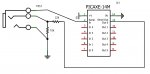
OK, I've been using PICAXEs for a while, but have always used header connectors on the PICAXE end. I have a project where I want to use the 1/8" phone jack for external programming of a PICAXE in a metal box. I went back the Manual #1...page 8. I was surprised to see that the "barrel" connection is Serial-out and not Common. In most all other electronics wiring the phone jack barrel is common/ground. Is there a reason?...like preventing shorting specific connections as the plug is inserted or withdrawn from a live serial-port to a live PICAXE.

A quick "search" turned up way too many threads about serial cables. :(

Ken
 

Andrew Cowan

Senior Member
This was talked about a while ago on the forum.

The answer is that telephone operators had lots of dangling wires, and it was designed so if the tip of the wire touched a metal table/desk, it wouldn't damage anything as the tip was ground.

That pinout went on to be used for digital cameras etc, became sort of standard for serial-3.5mm connectors, so that's what Rev-ed decided to use.

I think.

A
 

MartinM57

Moderator
I believe in the mists of time when Rev-Ed was searching for a suitable existing cable (rather than making one), the one that was found/selected was a 3.5mm stereo jack to 9 way D-type (when real serial ports ruled) that had the RS232 ground connected to the tip...and that's the way it's stayed.

It's been previously discussed on the forum (especially the bit about what happens when the earthed tip enters the socket first)...
 

KMoffett

Senior Member
So, without going through testing all combinations and permutations of contacts shorting, does anybody know what will happen if I rearrange the connections so the barrel is common. With serial from a USB adapter, is there any series resistance present to prevent damage to the adapter or the PICAXE while inserting the live plug...pulling TX, RX, or Serial-out to ground or +5V.

Ken
 

geoff07

Senior Member
Another function of the grounded tip is that the manual switchboard operator could tell if a line was busy by touching the socket sleeve of a line with the tip. She (usually a she) would then hear a click telling her that the sleeve had a voltage on it, which indicated that a line was busy - a very quick way of finding a free line. Bearing in mind that the ring and sleeve could both have 50 volts on them it doesn't seem that likely that the tip would be grounded for safety. It wasn't actually ground anyway, just a route to ground via the equipment.

When I first started using Picaxes I didn't realise this method of wiring was used and found it very frustrating until I learned.

I don't think it would be a good idea to ground an output that is delivering 5v. But you could add 250 ohms in series and I doubt the chip would notice, but this would limit the max short-circuit current to 20mA.

I suspect that you would be better off just accepting the design as it is.
 

KMoffett

Senior Member
My wish was to use a standard, non-isolated, panel mounted jack. That would require the barrel to be the common.

Ken
 

JoeFromOzarks

Senior Member
If you decide to create a different standard – a standard universally accepted in YOUR world, then live with it, stick with it and rock on.

I do not use the RTS (ring-tip-sleeve) programming connector.

Every one of my PicAxe designs, which command three programming pins - use a 3-pin (1-SerOut/2-SerIn/3-Gnd) male header. When I build a circuit using a (non-PicAxe) Microchip PIC with a 6-pin ICP/ICSP (1-MCLR/2-Vdd/3-Gnd/4-Dat/5-Clk/6-LVPPGM) for use with the PICKit3 I also use a header, but it’s 6-pin, not a 3-pin! The important part is I’m consistent between all of my designs.

‘Course, for the PicAxe stuff I decided to use a 3-wire CD-Audio cable as a programming link simply because I have a bucket full of ‘em. They mate with 2.54mm (pitch) spacing headers perfectly. Something like these: Mouser P/N 538-22-03-2161 I buy them in 40-pin combos and cut them to suit.

In the US audio industry, the SLEEVE part of the RTS is common, or ground.

:) joe
 
Last edited:

KMoffett

Senior Member
Joe,
I usually use 4 pin headers for programming. 1. Ground 2. Serial-in 3. Serial-out. 4. P-out
A three-pin female header plug using 1/2/3 for programming, and a two-pin jumper using 3/4 for operation.

Thanks all. I'll just have to try it...and watch for the smoke signals telling me I shouldn't have. ;)

Ken
 

inglewoodpete

Senior Member
I've tried to accomodate the existing cables into my hardware design.

The attached modified photo is part of the front panel of the controller box for Silent Barrage.

The front panel has a 10mm (3/8") hole drilled in it. I use the standard PCB mounted 3.5mm stereo socket that is recommended by Rev-Ed. I have fitted a HDPE black washer to the socket to help seal the hole, which should be visible in the photo.

Like Ken, I would prefer the sleeve to be earthed. However, I don't want to get cables mixed up between my many PICAXE projects. Maybe in the future there will be an insulated, threaded socket like those available for 6.4mm (1/4") plugs.
 

Attachments

hippy

Technical Support
Staff member
I doubt the PICAXE standard for the download cable jack is ever likely to change.

Perhaps the simplest option is to use a 1/4" jack socket and build a 3.5mm to 1/4" jack connection cable, then there can be no accidentally plugging a PICAXE standard cable into a socket which is wired some other way. Of course any suitable socket and inter-connect could be used.

One thing which needs to be taken into consideration is what a conductive chassis is actually connected to; it will connect to 0V via the sleeve of a jack, but mains earth may connect to the chassis as well.
 

aduy

Senior Member
when i did my first picaxe project i had actually switched the serial in and out on the download jack, and if i inserted the jack part way started the download and then inserted it fully it would start the download and somehow was able to run the programs. perhaps the picaxe is able to download through the serial out, but i dont know.
 

hippy

Technical Support
Staff member
Very odd things can happen with floating 0V's, parasitic power and crosstalk so I wouldn't discount it but it's hard to say why it worked or appeared to work.

Take a look at the hacksaw job I did with the "04M" and other previous "fun" where it doesn't matter which way round you connect 0V or +V as long as you don't choose the wrong pins. The PICAXE will think power is constant and unchanging and will see a fixed input signal changing depending on the supply signals so it's entirely possible to inject a download signal by only changing the supply signals. It seems plausible that the PICAXE could behave in such a way that the PC sees the download happening and keeps going at it.

Am I pointing upwards or are you upside down and I'm pointing downwards ? That might be more fun if left for one of our antipodean friends to answer :)
 

aduy

Senior Member
Perhaps two errors...one on each end of the cable? Two wrongs make a right!
it was only one error, because when i went to correct it i only reversed the wires serial in and out and then was able to download normally without using the partial insert of the cable method. and just for the record i recreated it and it still worked.
 

Attachments

MartinM57

Moderator
I guess the bets are off if you only partially insert the plug and you have a completely backwards download circuit, but rest assured, there's no way that the PICAXE is actually being programmed by having the program sent from the computer into the Serout pin.

Whatever you were doing, the program was going into the Serin pin and the PICAXE was responding on the Serout pin.
 

john2051

New Member
Hi,

Couldn't you use an insulating bush similar to the transistor insulating bushes?
Some of the ones I've seen for mounting high power diodes (50A) would fit, with some trimming. That way the standard download cables could still be used.

Something to think on....

Regards john
 

Haku

Senior Member
I once had a problem programming a Picaxe running off batteries, it responed fine when you did a firmware version query but failed when trying to program it.

Turned out I hadn't connected the GND line...!
 

KMoffett

Senior Member
OK, this is what I came up with...to have the sleeve/barrel at common ground. I had a concern about shorting the chip's serial-out pin in a 5V state when inserting or removing the plug while it's running. So, I made it the tip. It may briefly short the serial-out to the serial-in resistor network...but no problem. That left the serial-in on the ring. The bottom circuit is just my straight, sleeve-grounded, stereo jack. The top circuit uses a switched stereo jack, so the serial-out pin can be automatically switched for use as a program-output as soon as the plug is removed. http://www.radioshack.com/product/index.jsp?productId=2103451

Ken
 

Attachments

Last edited:
Top