Do-able by an 18M2?

Andrew Cowan

Senior Member
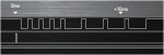
I'm working on a radio project, that requires me to generate a PPM pulse stream with the following timing requirements:

400uS Synch pulse
600-1600uS pulse for channel 1
400uS Synch pulse
600-1600uS pulse for channel 2
400uS Synch pulse
600-1600uS pulse for channel 3
400uS Synch pulse
600-1600uS pulse for channel 4
400uS Synch pulse
600-1600uS pulse for channel 5
400uS Synch pulse
600-1600uS pulse for channel 6
400uS Synch pulse
600-1600uS pulse for channel 7
400uS Synch pulse
600-1600uS pulse for channel 8
400uS Synch pulse

Read 4 potentiometers

Repeat sequence.

This al needs to run in a 22mS cycle - so a worst case of 5.6mS to read the potentiometers.

For an 18M2 running at 32MHz, using pulseout, this all looks easily acheiveable - can anyone see any problems/issues I might come accross?

Thanks

Andrew
 

hippy

Technical Support
Staff member
I'd imagine it were possible. The caveats are how accurate do you need the pulses, are they out of a single pin or multiple, is there any gap between the pulses, how much ?

The obvious solution would be a linear sequence of PULSOUT but then each may have slightly different timing depending on token position. Put that in a loop and you'll add delays between pulses.

This looks similar to how I was doing IR control for my TV etc and I ended up using a 20X2 and building the bitstream with time between toggles in scratchpad then churning that out in a tight loop in a subroutine at the start of program code so timing stayed constant. It was a fair bit of effort to optimise the code to be fast enough but I can't recall how fast I needed.
 

Andrew Cowan

Senior Member
I'm aiming for something similar to the attached scope image.

The signal is idle high - the sync pulses are negative, then the data is positive. The accuracy of the width of the sync pulses is not as important as the accuracy of the data pulses - for that reason, I think it would be best to use pulsout for the data, possibly like the below code. The reason for this is so (hopefully) the length of the channel pulses will be very accurate - I'm not to bothered in the accuracy of the length of the sync pulses.

Hippy - when you say the length of pulseout varies with token position, what magnitude of variation are you talking about (say at 32MHz)?

Does the below code seem right/acceptable?

Code:
do
low pin
pauseUs 400
pulsout pin, channel_one_width
pauseUs 400
pulsout pin, channel_two_width
pauseUs 400
pulsout pin, channel_three_width
pauseUs 400
pulsout pin, channel_four_width
pauseUs 400
pulsout pin, channel_five_width
pauseUs 400
pulsout pin, channel_six_width
pauseUs 400
pulsout pin, channel_seven_width
pauseUs 400
pulsout pin, channel_eight_width
pauseUs 400
high pin
'read all inputs, calculate new times
pause remaining time

loop
Thanks

Andrew
 

Attachments

Last edited:

hippy

Technical Support
Staff member
Thanks for the clarifications. It does look possible. I'm not sure of the effects of token positioning with the 18M2 so that would need some testing / observation.
 

hippy

Technical Support
Staff member
A quickly thrown together test, numbers chosen to get roughly the right ball park -

Code:
#Picaxe 18M2
#No_Data

Symbol SYNCH_400us  =  200
Symbol PULSE_600us  =  500
Symbol PULSE_1600us = 1300

SetFreq M32 
High    C.0
Do
  PulsOut C.1, 100                                ' Scope sync
  PauseUs SYNCH_400us : PulsOut C.0, PULSE_600us  ' 1 
  PauseUs SYNCH_400us : PulsOut C.0, PULSE_600us  ' 2 
  PauseUs SYNCH_400us : PulsOut C.0, PULSE_600us  ' 3 
  PauseUs SYNCH_400us : PulsOut C.0, PULSE_600us  ' 4 
  PauseUs SYNCH_400us : PulsOut C.0, PULSE_1600us ' 5 
  PauseUs SYNCH_400us : PulsOut C.0, PULSE_1600us ' 6 
  PauseUs SYNCH_400us : PulsOut C.0, PULSE_1600us ' 7 
  PauseUs SYNCH_400us : PulsOut C.0, PULSE_1600us ' 8 
  Pause 4000
Loop
Measured results were ...

Code:
' Gap (ns)  Ch    Pulse (ns)
' 
'            1     626063
' 410128     2     626063
' 405250     3     626188
' 401313     4     626125
' 405313     5    1626188
' 405250     6    1626125
' 405250     7    1626000
' 405188     8    1626063
 

Attachments

Andrew Cowan

Senior Member
Many thanks for trying that - that accuracy is going to be fine for my application.

Once I've got my PCB, I'll have to do some experimentation to determine how long the readadc's take, but that shouldn't be too hard.

Am I right in thinking you're using the saleae logic analyser? I think I might need to add one to my test equipment set...

Andrew
 

hippy

Technical Support
Staff member
Four READADC are around 500us, ~125us each, so won't be a problem. You could also interleave them as part of the sync pulses.

Yes, that's the Saleae "Logic" analyser. For the price we have found them absolutely superb, and part of that cost are the professional 'EZ-Hook' connectors. I wouldn't want to attempt time critical bit-banging code like this without a logic analyser or a digital scope. With the Saleae the READADC timing test was just a few seconds of effort, and it has easily paid for itself.

http://www.saleae.com
 

Andrew Cowan

Senior Member
I've got a digital scope (Farnell's PDS5022S that was talked about recently) - it's a great bit of equipment, with the only downside being the storage - storing only 5K points, it's not freat for looking at long streams. However for short measurements it's fine.

Andrew
 
Top