DIY Rotary encoder

Rickharris

Senior Member
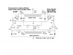
I have had a need for a rotary encoder to turn the rotations of a knob into some kind of digital signal.

I needed to know the direction of turning and how many times the knob is turned.

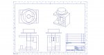
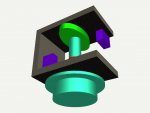
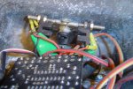
I have, after some experimentation, come up with the attached which seems to work OK in my lash up at present and now moves to the better engineered stage to improve the looks. The idea may be useful to others.

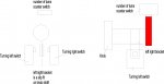
The knob is attached to a shaft, on the shaft is a friction collar - tight enough to operate the micro switches but loose enough to slip once the micro switch is reached. A cam operates another microswitch to allow a count of the number of turns.

The programme simply monitors the left right switch to decide direction and then counts the turns.
 

Attachments

Andrew Cowan

Senior Member
Is the red cam in the 3D image the same orientation as the green cam?

Also, do the switches press against the cams when it is centred? That would mean it alwys sprung back to the centre position.

A
 

gengis

New Member
Nice job.

Nuts and Volts had an article years ago that used a small stepper motor for a rotary, quadrature, encoder. Takes a 1/4" knob and outputs a signal to a counter. The ingenious designer simply used the U/D input for one of the coil outputs, if that coil was + while the count input (other coil was positive) it was going CCW, etc..

Another off-label use for steppers is remote positioners . . . without a lot of extra circuitry. (called synchros years ago) One stepper generates the signal for the second and the remote motor follows the actions of the local one. Attached circuit lacks Flip Flops which would give the remote stepper holding torque.
 

Attachments

Rickharris

Senior Member
Is the red cam in the 3D image the same orientation as the green cam?

Also, do the switches press against the cams when it is centred? That would mean it alwys sprung back to the centre position.

A

The green cam is fixed to the shaft and rotates with it. In this case it will contact the microswitch twice every revolution of the knob.

The green cam - What I call a collar is fixed to the shaft but not tightly - It will turn with the shaft until it reaches the micro switch and is just tight enough to operate the microswitch - also gives some "feel" to turning the knob -

Depending on which micro switch it touches it tells me which way the knob is turning. the green cam gives the count of how many turns. there is no centre position as such. The micro switches pushed off the red cam enough to rest it if you stop turning but I may put a light elestic band on the finished article to centre it.
 

hippy

Technical Support
Staff member
@ Flooby ( with apologies to Rickharris for thread diversion )

Never thought of this as a use for steppers. I have a number culled from old VCR's gathering dust so put a LED straight across a coil and - voila - LED comes on when turned fast enough.

With the sacrificial 08 brought out for random punishment, 0V to one side of the coil, other to a TTL input pin and a pull-up R, PULSIN is reading something on every other 'detent' of the stepper as it is turned ( most times ). Didn't work so well with an ST input.

Not the best electrical interface ( I have no idea what signal it is putting out, particularly polarity and peak voltages ) and not the best test harness code, but that does look like a promising concept to pursue for anyone with some spare time on their hands.

READADC also gives some interesting results as well. Probably even more interesting on an 08M which isn't just 4-bit ADC.
 
Last edited:

leftyretro

New Member
@ Flooby ( with apologies to Rickharris for thread diversion )

Never thought of this as a use for steppers. I have a number culled from old VCR's gathering dust so put a LED straight across a coil and - voila - LED comes on when turned fast enough.

With the sacrificial 08 brought out for random punishment, 0V to one side of the coil, other to a TTL input pin and a pull-up R, PULSIN is reading something on every other 'detent' of the stepper as it is turned ( most times ). Didn't work so well with an ST input.

Not the best electrical interface ( I have no idea what signal it is putting out, particularly polarity and peak voltages ) and not the best test harness code, but that does look like a promising concept to pursue for anyone with some spare time on their hands.

READADC also gives some interesting results as well. Probably even more interesting on an 08M which isn't just 4-bit ADC.
I've seen a few adaptions of converting stepper motors to encoders. It has a couple of drawbacks. It could use good analog comparators to switch consistently as the voltage developed from the windings is dependent a lot on shaft speed, and there is a need of memory elements (flip flops) to hold the state at rest as all position information is lost once the shaft stops turning.

Lefty
 

gengis

New Member
This may be going further afield . . . but the stepper encoder, as mentioned, is speed dependent. That's the reason for using an op amp to digitize the signal. The opamp in the synchro schematic is biased at 1/2 VCC (the one K resistors between + and ground). Op amps have open loop gains (the way it is used - with no gain limiting resistors) on the order of 200,000. With that kind of gain, you can't (for all practical purposes) turn the encoder slow enough (at least not with human hands) to not get an output. The only caveat - put some protection on the input to the circuit, because a quick spin may exceed the safe input voltage. A diode clamp is a must.

I designed and built the synchro starting with just darlington transistors to do the switching and it wouldn't track at low speeds - the quad op amp does work.

You have to avoid strong magnetic fields because the motor sheilding may pick up some hum from transformers and such - putting the two synchros back to back will cause the motor to turn continuously - from the feedback through the magnetic field - but that's only if they are closer than 1/2".

As also mentioned steppers make dandy little AC generators.
 

hippy

Technical Support
Staff member
Good point about being speed dependent. I imagine the way it is working is by turning a magnet to induce a current in a coil, do that too slowly and there won't be much of a pulse to detect.

In my tests there was a consistent 'something' being seen even on fairly slow turns except when I artificially slowed it down from jumping to its next natural resting place. It seemed to be good enough to be usable as an infinitely variable pot for volume control or similar.
 

Rickharris

Senior Member
Good point about being speed dependent. I imagine the way it is working is by turning a magnet to induce a current in a coil, do that too slowly and there won't be much of a pulse to detect.

In my tests there was a consistent 'something' being seen even on fairly slow turns except when I artificially slowed it down from jumping to its next natural resting place. It seemed to be good enough to be usable as an infinitely variable pot for volume control or similar.

I would like to be able to say that's why I used a micro switch - But I didn't think of using a stepper that despite knowing I do a demo of generation using a stepper and LED at school.

I guess I could use a reed relay if I wanted a no contact but the click of the micro switch kind of makes the action more real (to me anyway)

Could of course use grey code for absolute position but the simple answer is good enough for my purpose - I intend to use it to simulate the rotary knob input to tunr a virtual radio.
 

Tom2000

Senior Member
If you'd care to try your hand at a homebrew optical encoding solution, perhaps one of the quadrature encoder with index pulse codewheel variants of my Codewheel Generator program might be of some use to you.

With a codewheel you print on your printer, you can cobble upi something simply and cheaply. And it will have much better reliability than your mechanical solution, with no maintenance or adjustment requried.

Good luck!

Tom
 

flyingnunrt

Senior Member
Hi Rick
Here is a quad encoder I made up out of a couple of photo interupters and an old pot housing with half a servo disk glued to the shaft.
It was only intended as a proof of concept but it worked OK and was used for the proto unit.
Excuse the dust. The project still needs to be tidied up a bit... when I get time.
It counts single turns of the shaft and uses the program code to work out if it's going CW or CCW.
With an 18X overclocked to 8Mhz it works quite well and with a bit of grease in the bearing has very little friction.
So far, on test, it has not missed a single clock.
 

Attachments

Rickharris

Senior Member
If you'd care to try your hand at a homebrew optical encoding solution, perhaps one of the quadrature encoder with index pulse codewheel variants of my Codewheel Generator program might be of some use to you.

With a codewheel you print on your printer, you can cobble upi something simply and cheaply. And it will have much better reliability than your mechanical solution, with no maintenance or adjustment requried.

Good luck!

Tom
thanks tom I always considered the alignement problems were too hard to bother about so never considered such an elegant solution - More experimentation to do!!! :)
 

Rickharris

Senior Member
Hi Rick
Here is a quad encoder I made up out of a couple of photo interupters and an old pot housing with half a servo disk glued to the shaft.
It was only intended as a proof of concept but it worked OK and was used for the proto unit.
Excuse the dust. The project still needs to be tidied up a bit... when I get time.
It counts single turns of the shaft and uses the program code to work out if it's going CW or CCW.
With an 18X overclocked to 8Mhz it works quite well and with a bit of grease in the bearing has very little friction.
So far, on test, it has not missed a single clock.

thanks FN Ill keep it in mind. How does the knob fit onto the shutter?

Not clear from your dusty photo- or maybe its my glasses as UI have been in the shed. ;)
 

Rickharris

Senior Member
Just as a passing comment I didn't say what I was doing at the top of all this ( forgive me), I have embarked on building a motion platform for Microsoft flight simulator FSX.

The target is for a light aircraft simulation - I have researched extensively and am impressed by some of the vast Jumbo jet simulator people have in their houses (obviously a more understanding partner than I have!) but this is not my aim or interest.

The initial work to prove concept has produced a mechanical solution that seems to work OK with 2 deg of freedom - pitch and roll - although a second more compact version is partially built.

The next stage is to motorise it and use a picaxe as the interface between the motion platform and the flight inputs i.e the pilot and the flight simulator software.

I also intend in the longer term to make a fully operational instrument panel using 1 or 2 08M's to drive each instrument based on information from the flight simulator software.

Mmmm - Budget tiny - expectation high! ever hopeful :)

If it all goes well than a 3rd version may run to adding a 3rd deg of freedom but I am not sure this is necessary.
 

Marcwolf

Senior Member
Hi..
I was looking at the quad encoder and thinking. If you have a wheel with multiple vanes on it you can increase the resolution very easily.

Also - if you don't place the two optocoupler units at 180o, but say at 175o, then by seeing which optocoupler unit is fired first you can work out the direction of the spin as one would be fired first depending on spin.

Has some interesting possibilities. Thanks for sharing

Dave
 

flyingnunrt

Senior Member
Rick
The knob is on the other side of the glassfibre wall that the pot shaft passes through. I hacked the back off the pot but the mounting method is as per normal locking nuts.
Yes more vanes could be used but this is what was required for my project.
 

Andrew Cowan

Senior Member
Also - if you don't place the two optocoupler units at 180o, but say at 175o, then by seeing which optocoupler unit is fired first you can work out the direction of the spin as one would be fired first depending on spin.
Although that assumes the speed is constant...

A
 

hippy

Technical Support
Staff member
I don't think speed affects anything at all. As long as the sensors ( be they optical or physical ) do not activate at the same time, one sensor's change will always precede the other.

Note there's a difference between a vane or cam driven switching and pointer driven switching; the first allows for a quadrature encoder, the second does not ( except with external hardware or software processing ) . Which is best or most suitable depends on application and requirements.
 

Tom2000

Senior Member
thanks tom I always considered the alignement problems were too hard to bother about so never considered such an elegant solution - More experimentation to do!!! :)
Rick,

There are a couple of solutions to the alignment problem.

The first is the two-track quadrature wheel, or the two-track quad wheel with index track types I incorporated into the Codewheel program specifically to simplify alignment of a quad encoder. With one of these two-track wheels, all you need is a pinhole mask. It's easy to align holes.

An even better solution is the Honeywell HLC2705 IC, that contains two IR photodiodes and quad decoding circuitry onboard. The beauty of that little chip is that you can use a single track wheel, a single photodetector chip, and absolutely no alignment at all! Wire leads provide mounting flexibility.

For turns counting, you'd use an extra IR LED and photodiode for the index track. Those wouldn't require any critical alignment at all.

Have fun!

Tom
 

Tom2000

Senior Member
I don't think speed affects anything at all. As long as the sensors ( be they optical or physical ) do not activate at the same time, one sensor's change will always precede the other.
Yes, exactly.

A quad decoder is a state machine.

If you trigger your "look" at the state of the encoder at any transition of the two photodetectors, you'll find that the two tracks can have only four possible states at that transiton: 00, 01, 11, and 10. And the states occur in that sequence when the encoder is rotated clockwise, let's say. For counterclockwise rotation, the very same states would occur in the reverse order.

So decoding a quad encoder is simply a matter of initially measuring and storing the current state at initialization.

When your decoder detects a transition, look at the state table. If the measured state is the one immediately preceeding the previous state, the rotation is counterclockwise. If the measured state is the on immediately following the previous state, the rotation is clockwise. If neither of these apply, you've missed at least one transition.

Save the current state to use as the previous state at the next transition, and Bob's your uncle.

I've included a fairly extensive tutorial on this stuff on my Codewheel Generator Program page.

Tom
 
Top