And a few hints and tips for new and old . . .
DIPTRACE PCB CAD PACKAGE
There are a lot of excellent schematic / pcb CAD programs on the market. Your choice depends on your budget, the amount of time you plan on spending learning the commands, the type of output you want and the overall ease of use and "look" of the program.
I had heard a lot of good things about EAGLE, and after 3 years of working with EAGLE I was finally able to get EAGLE to do the things that I wanted in reasonably quick amount of time. I must admit that I am not a novice user or nor are my projects very simple.
Because of my frustration with the reverse logic in the EAGLE interface, I kept trying other software.
If you are looking for a schematic CAD program, think about the readability of your schematic and the ease of creating it.
Mycroft came across DIPTRACE, downloaded the demo and converted from EAGLE in less than a week. It was that easy to use. Very windows like commands and a very intuitive interface.
But the main selling point for me was the ease of creating components and footprints. I was tired of the generic square boxes with letter and numbers for component symbols. These boxes are very hard to understand and how they relate to the real world.
There is a free download at
www.diptrace.com
This free version allows any size pcb to be made that contain a maximum of 250 pins and 2 layers.
There is also an exact size printout function that is great of toner transfer or photo homebrew pcbs.
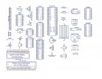
Mycroft has created a library with a set of new components in the 'live-bug" style along with some pcb footprints that were easier to use in homebrewed pcb boards.
The library comprises all of components used in the Rev-Ed manuals and then some.
The pads are oversized to be more forgiving when hand drilling.
FILENAME EXTENSIONS FOR UPLOADING AND USE:
Due to the limitation of the PICAXE forum. The .lib and .ele extensions cannot be used to place files on the forum. It is recommended that everyone use the file extension “.dsn” (the standard trick to post non-conforming formats on the forum).
When downloading the library files for use remember to change the file extensions back to .eli or .lib as the poster has indicated.
TEXT FOR COMPONENT IDENTIFICATION:
The PICAXE 40X text seems to be embedded into the symbol data
The text is part of the component on the 40X and can be changed in the component editor.
TEXT ALIGNMENT:
Are you having difficulty placing text to line up accurately and closely with the component pins.
The easiest way to adjust the text placement is to change the grid size to something like 0.001", move the text then change the grid size back to a standard 0.10" or 0.05" grid.
COMPONENTS – STEREO SOCKET:
In the Mycroft schematic symbols library, note that one of the pcb patterns for the stereo jack was meant to be a generic footprint, just a 3 pin header.
There is a separate component symbol for the pcb mount jack that Rev_Ed uses.
MULTIPLE-PART COMPONENTS:
The standard DIPTRACE supplied libraries contains some components such as logic gates and the IDC type headers listed as 2 x 7 and 2 x 8 in male and female. If selected, they show up okay as a PCB footprint, but when placed only one half of the connector is shown on the schematic with each insertion.
Two options to place the parts.:
1. placing multiple symbols and then identifying as part 1 and part 2 in the properties.
2. To place all parts on the schematic simultaneously, you will find in the upper left corner of the schematic editor is a check box, "Place all Parts"
That will automatically put all the parts of a component on the sheet at one time, otherwise YOU CAN select which part from the box above.
") (but significantly cheaper and to suitable quality)
(but significantly cheaper and to suitable quality)