Dimming AC with PWM

69-cat

Member
So having some problems getting this to work. I have been using MOC3041 along with a 4 amp Triac to control basic on/off or flashing/ strobing an AC lamp but thought using the zero-cross opto-coupler would be able to work with the MOC3041 but it flashes instead of ramping up and down. I even tried using a "pre-built" circuit but with the same outcome. The only thing I am not sure of is the pre-built has 4 connections +, -, signal (PWM) and a forth marked Z/C. Can someone shed some "light" on what I may be doing wrong?
Dave
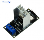
26143
 

papaof2

Senior Member
I suspect "Z/C" is a place for a zero crossing sync signal either incoming or outgoing. I've not used that chip so that's all I can help with - check the datasheet.

PWM with AC will definitely require synchronization of the PWM signal with the AC waveform or the power out of the triac will be garbage..

For a very bad example, try using a halogen lamp with a dimmer on a modified sine wave DC-AC inverter: neither is happy with that combination. However, it works just fine with a pure sine wave inverter where there is a cleanly defined zero crossing in the waveform.
 

fernando_g

Senior Member
1- You *cannot use* a zero crossing optocoupler driving a Triac for either PWM or phase-control of an AC load. By it’s very nature, only integral cycle is possible.

2- Random trigger triac optocouplers driving Triacs should be used for phase control of AC loads.

3-If you want PWM control of an AC load, neither device can be used. Use one of the isolated IGBT drivers, driving an IGBT, not a Triac.
 

Jack Burns

New Member
From the limited information I have seen...

Z/C is a zero crossing output that is connected to a microcontroller interrupt input. The interrupt routine then sends a brief output signal to the PSM terminal to turn the triac on, this results in it staying on for the rest of the mains half cycle.

This process needs to be repeated at every zero crossing and effectively give the same output as a conventional light dimmer.
 

lbenson

Senior Member
Some years ago I used one of these modules to model implementing "soft start" on an AC motor. The picaxe (at the fastest speed possible) responded to the zero-crossing interrupt by first turning on the triac near the end of the half-cycle and then reducing the delay time until it was full on (I don't remember how many steps--maybe between 8 and 16 depending on how many picaxe instructions could be run in the half-cycle).

You should be able to respond to the zero-crossing interrupt to turn the triac on for the desired percentage of the half-cycle.
 

fernando_g

Senior Member
I should have better explained myself.
The OP was originally using a MOC3041, which it has an internal zero-crossing circuit. It will not turn on unless the zero crossing has been reached. Thus it can only control whole cycles. It won’t due phase control, much less PWM.

OTOH, the ebay module has a MIC302? device, which can be arbitrarily fired at any point of the sinewave. A properly synced microcontroller can perform phase control to achieve a continuously variable power level.
 
Top