Digital logic on noisy lines

Circuit

Senior Member
I need to send 8 lines of digital logic over some long wires; 20 to 100 metres perhaps, as part of a security system. PICAXEs will be at either end. The lines are in a domestic environment but may be passing a variety of other cables, mainly mains cables, washing machines and so forth, and therefore I am a little concerned about noise and inductive pickup etc.

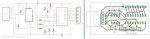
I am reluctant to use optocouplers because the system must have a long lifetime and the optocoupler emitters would be on for 99% of the time. Optocouplers follow a decay curve and I don't really want to get into trying to calculate a lifespan and planning in the overhead necessary to compensate for decay. Therefore I am proposing to hold the interconnects at 12 volts with TBD6203APG s with 10K to 12v on each wire. Another TBD6203APG at the other end will interface back to 3.3v for the receiving PICAXE. Diagram herewith.

long noisy cables.png


The TBE62083APG is a modern DMOS replacement for the ULN2803A and its characteristics seem to match these requirements better. Does this appear to be a sensible approach? Critique and expert comments or alternative suggestions would be very welcome.

(Edited to correct for embarrassingly silly mistake pointed out by Technical below.)
 
Last edited:

Technical

Technical Support
Staff member
This won't work with open collector outputs, you have nothing here to pull the lines into a high state.
 

hippy

Technical Support
Staff member
Rather than send 8-digital signals in parallel, it might make sense to combine those into serially sent bytes, using MAX3232 buffers or similar, perhaps a balanced line, to minimise any problems with noise. The sending system can package up the bits to send, the receiving system can unpack those.

If you spread the 8-bits across two bytes and add a CRC that should give good reassurance you are getting valid data.. You can send data multiple times just to make sure.

Code:
Symbol TX      = B.7
Symbol TX_BAUD = N2400

TransmitTest:
  Do
    For b0 = 0 To $FF
      Gosub SendB0
      Pause 1000
    Next
  Loop

SendB0:
  ; Sends 0 0 1 1 0 0 1 1
  ;       0 1 0 1 d c b a
  ;       1 0 1 0 h g f e
  ;       1 1 x x x x x x
  b1 = b0 & $0F | $50
  b2 = b0 / $10 | $A0
  b3 = -b1 * 2 + b2 | $C0
  SerOut TX, TX_BAUD, ( $33, b1, b2, b3 )
  Return
Code:
Symbol RX      = C.0
Symbol RX_BAUD = N2400

ReceiveTest:
  Do
    Gosub ReceiveIntoB0
    SerTxd( "Got ", #bit7,#bit6,#bit5,#bit4, " "    )
    SerTxd(         #bit3,#bit2,#bit1,#bit0, CR, LF )
  Loop

ReceiveIntoB0:
  SerIn RX, RX_BAUD, ( $33 ), b1, b2, b3
  If b1 < $50 Or b1 > $5F Then ReceiveIntoB0
  If b2 < $A0 Or b2 > $AF Then ReceiveIntoB0
  If b3 < $C0             Then ReceiveIntoB0
  b0 = -b1 * 2 + b2 | $C0
  If b3 <> b0             Then ReceiveIntoB0
  b0 = b1 & $0F
  b0 = b2 * $10 | b0
  Return
Edit: Changed the magic numbers
 
Last edited:

lbenson

Senior Member
Rather than send 8-digital signals in parallel ...
Or perhaps boosted I2C with an P82B715 I2C-bus extender to an MCP23008 for 8 digital signals or MCP23017 for 16 signals. Tested by me to 50 feet over CAT5/6 cable.

If interested, I have an MCP23008 PCB design I can share.
I2CExtenderMCP23008.jpg
I2CExtenderMCP23008_image.jpg
Or perhaps I2C directly to a picaxe X2 i2c slave,
 
Last edited:

Circuit

Senior Member
This won't work with open collector outputs, you have nothing here to pull the lines into a high state.
Oh dear, I need to rethink... Well that is an embarrassing schoolboy error indeed. Okay, rather than delete my enquiry with sheer embarrassment, how about if I keep the same idea but connect the 10 K pull-ups to 12 volts+ve? And, of course, pull-ups on the receiving PICAXE pins. (Crikey, I am red-faced...) Do I now have a robust system?

Thank you for the suggestion regarding RS232, Hippy and for the code. And Ibenson for the I2C idea. I had already considered RS485 which I am using to some degree at the moment but I want simplicity, reliability and robustness. A further problem is that I cannot re-cable but must use a variety of existing cables.

I guess that I have asked half a question in that I might have more than one PICAXE running, say, some with three outputs, some with four and with more than eight inputs spread across another TBE62083APG, probably culminating in a 40X2. My question is really that I am looking at the principle only; are there any drawbacks in having such a buffer arrangement or any reason why it will not work? I am not looking at transmitting complex information; just a digital change of state and I have no shortage of pins. Furthermore, if a wire is cut then the line drops and that is detected; not so easy with RS485 nor I2c.

Ibenson, your project interests me for another item I am working on. Unfortunately, 50 feet is not adequate for my security system, but I shall study your schematic further. I have used MCP2300xx chips on I2C but never with an extender - I shall download the datasheet for the P82B715 I2C and perhaps come back to you with further questions; thank you for the images.
 
Last edited:
Top