Absolutely.
They are a good idea in any circuit and manadatory in noisy circuits.
A well rounded pukka circuit will also have decoupling on the reset pin too.....
When used as chip decoupling there are several things to consider, including:-
1. Noise from circuit getting into chip.
2. Noise from chip getting into circuit
3. In some cases crowbar pulses (e.g. old 555).
A good ceramic capacitor 'diverts' a lot of HF noise as it is appears as an easier route for HF AC.
An electro or tantalum in parallel acts as a reservoir for crowbar or LF/transients coming from power line.
These should be close to chip so that the PCB track effects are minimal.
ADCing? Fit decoupling. Get rid of noise in and out of PICaxe. You'll thank me later.
")
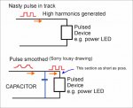
The bits which most people forget are when they have relays or power LEDs (or any noisy thing) in the circuit - especially where sharing a power track on a PCB.
My awful drawing shows a general pulsed device - this could be a power LED.
A relay could be even worse.
REMEMBER: at switch-off the Back-EMF diode will shunt a nasty spike onto the power line.
The capacitor can help to absorb that and prevent it getting to other places in your circuit.
(Obviously , the magnitude will depend on PSU 'strength' , proximity and layout so let's not get too pedantic).
THINK of each track/wire as an Resistive conductor which can transmit and radiate noise.
THEREFORE placing a capacitor in strategic places makes it an RC filter.
AND placing the capacitor
'locally' keeps the noise and high harmonics and transients in a small patch.
THINK of capacitors as a HF noise diverter and reservoir.
NOTE different type capacitors have different characteristics.
It's a BIG subject as 'good practice' also encompasses track layout and good ground techniques, shared lines, proximities etc.
As well as paralleling ceramics in some RF circuits.
It could go on for pages and I'm puffed out.
(Sorry, I did this in a rush, hope it makes vague sense)