Decoding "sertxd" and "serin" on a scope.

Sean87

Member
Hi all,

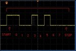
At the moment I am working with a simple ADC using a pot and transfering the result to a PC. I am using normal download ciruit and I am able to receive ASCII numbers on the terminal. The settings are 9600/None/8/1. Now I am trying to capture the waveform in my scope. I captured waveforms below:

0:


255:


So my questions are:
1- Am I capturing right waveform (timebase and stuff...)
2- How to decode tese waveforms? I beleive it is not binary and it is ASCII already. Right?

Thanks!
 

srnet

Senior Member
ASCII is (normally) sent as binary.

Try sending a capital 'U', this is 01010101 in binary, and will give you clues as to the right bit pattern.

A single space " " is 00100000 in binary, so compare with that.
 

Sean87

Member
Depends on your code - please post it...
This is my code:

Code:
let adcsetup = %0000000100000000
let dirsc = %00001100

main:
readadc c.1,b1
sertxd (#b1, CR)

SELECT b1

CASE 0
low 0,1,2,3,4,5,6,7,c.2,c.3

CASE 1 TO 25
low 1,2,3,4,5,6,7,c.2,c.3
high 0

CASE 25 TO 50
low 2,3,4,5,6,7,c.2,c.3
HIGH 0,1

CASE 50 TO 75
low 3,4,5,6,7,c.2,c.3
HIGH 0,1,2

CASE 75 TO 100
low 4,5,6,7,c.2,c.3
HIGH 0,1,2,3

CASE 125 TO 150
low 5,6,7,c.2,c.3
HIGH 0,1,2,3,4

CASE 150 TO 175
low 6,7,c.2,c.3
HIGH 0,1,2,3,4,5

CASE 175 TO 200
low 7,c.2,c.3
HIGH 0,1,2,3,4,5,6

CASE 200 TO 225
low c.2,c.3
HIGH 0,1,2,3,4,5,6,7

CASE 225 TO 245
low c.3
HIGH 0,1,2,3,4,5,6,7,c.2

CASE > 245
HIGH 0,1,2,3,4,5,6,7,c.2,c.3

ENDSELECT

goto main
 

hippy

Ex-Staff (retired)
Note that the sertxd stream is "inverted rs232 logic" i.e. makes actual sense in that high = data value 1, low = data value 0 :D
Actually ... SERTXD data output is N4800 or N9600 in PICAXE terminology; idle low (0V), the actual data bit valuess will be 0V = 1, +V = 0. The data stream is sent as follows; idle (0V), 'start bit' (+V), lsb (bit0) to msb (bit7), 'stop bit' (0V), idle / inter-byte gap (0V).

It's best to adjust the scope or logic analyser so a single bit is the width of a horizontal graticule so you can quickly tell the number of bits in highs and lows greater than a single bit length.

It's far easier to use a terminal emulator or a scope / logic analyser which can work out what the data is rather than determine it by hand. Which brings us to the $64,000 questions - why do you want to do this ? What problem are you having or hoping to solve ?
 

Sean87

Member
Actually ... SERTXD data output is N4800 or N9600 in PICAXE terminology; idle low (0V), the actual data bit valuess will be 0V = 1, +V = 0. The data stream is sent as follows; idle (0V), 'start bit' (+V), lsb (bit0) to msb (bit7), 'stop bit' (0V), idle / inter-byte gap (0V).

It's best to adjust the scope or logic analyser so a single bit is the width of a horizontal graticule so you can quickly tell the number of bits in highs and lows greater than a single bit length.

It's far easier to use a terminal emulator or a scope / logic analyser which can work out what the data is rather than determine it by hand. Which brings us to the $64,000 questions - why do you want to do this ? What problem are you having or hoping to solve ?
Well I only want to learn the idea of serial communication, specially how 20X2 transfers data and also I am thinking for off-PC debugging abilities of myself :p

So you mean I am not on the right timebase on my scope? can you give some numbers please?

Thanks.
 

hippy

Ex-Staff (retired)
You can use whatever timebase you want, that's just a tip I find helps. From baud rate you can determine the bit time in seconds ...

bit time = 1 / baud rate

To study SERTXD output, understand RS232, use a very simple program, output %11010110 repeatedly ...

Do
SerTxd( %11010110 )
Pause 100
Loop

That way you'll only have one data byte and you know what its value is, can then correlate what you see to the data you are sending. You should see something like ...

Code:
      ___     _   _
_____|   |___| |_| |_________

      S 0 1 1 0 1 0 1 1 P
Change the value sent and see the result on the scope, check how that correlates.
 
Last edited:

Sean87

Member
Thanks this was a nice tip. I got the same waveform as yours:


Now the question is what is wrong with my first post waveforms? Why are they much longer ( I guess they both have CR bit at theire end?)
 

hippy

Ex-Staff (retired)
There's possibly nothing wrong with your first waveforms, but unless you can identify where the data starts ( which are the start bits ) it's hard to work out what the trace shows.

There's more data sent because #var will send between 1 and 5 bytes of data plus CR and LF will be extra bytes as well.
 

hippy

Ex-Staff (retired)
If you can adjust the timebase ( each graticule segment ~= 104us rather than 100us ) you'll align each bit on a graticule edge, can then easily tell where the bits fall. That's usually easy on an analogue scope and I'd guess a digital scope offers similar ...
 

Attachments

Paix

Senior Member
ascii data.jpg
The start and stop bits are identified, but aren't too clear in my annotation of your scope picture, and the data bits are between. The start bit is the first after the idle condition which is apparent in the first character but not quite as evident on the second.

The rest is ascii code lookup.

Regards.

10110011 = 3
01010011 = S
01010011 = S
1001111 = O
Unless I'm inverted of course. Murray code is more familiar to me off the top of my head.
 
Last edited:

Sean87

Member
View attachment 8713
The start and stop bits are identified, but aren't too clear in my annotation of your scope picture, and the data bits are between. The start bit is the first after the idle condition which is apparent in the first character but not quite as evident on the second.

The rest is ascii code lookup.

Regards.

10110011 = 3
01010011 = S
01010011 = S
1001111 = O
Unless I'm inverted of course. Murray code is more familiar to me off the top of my head.
Thanks for comment, but with that waveform I was receiveing "255" at terminal + new line feed..something like:
255
255
255
255
255

Thanks for taking the time!
 
Top